Continue to Site

Welcome to our site!

Electro Tech is an online community (with over 170,000 members) who enjoy talking about and building electronic circuits, projects and gadgets. To participate you need to register. Registration is free. Click here to register now.

  • Welcome to our site! Electro Tech is an online community (with over 170,000 members) who enjoy talking about and building electronic circuits, projects and gadgets. To participate you need to register. Registration is free. Click here to register now.

Voltage Comparator

Status
Not open for further replies.

andy257

Member
Hi Guys

Can someone who knows what their talking about explain the function of this circuit for me. Here is what i think it does:

Intro:

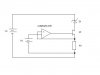
D1 is a 2.5V shunt regulator. The whole purpose of this circuit is to test the diode to see if its doing what its spec says it should. Between 400uA and 10mA the didode should have a rock steady voltage of 2.5V.

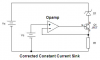
Basically the op amp inverting pin is supplied with a voltage so that it turns the fet hard on and appears across r1. A current is produced and flows through D1. This whole circuit is acting like a constant current circuit.

e.g 10 volts supply into the comparator, r1 = 1K, the current flowing will be 10mA through the diode.


What i dont understand is what does the feedback do? I know if the inverting pin is higher than the non inverting pin the output is high.

How does this circuit control itself, threough the feedback but how does it work?

cheers guys

Andy
 

Attachments

  • voltage_comparator_366.jpg
    voltage_comparator_366.jpg
    10.9 KB · Views: 618
It's a constant current source, the comparator keeps the voltage constant across the resistor, and as the resistor is constant, the current must remain constant as well (simple ohms law). By adjusting the voltage on the other comparator input, you can set the voltage across the resistor (and hence the current through it).
 
Nigel Goodwin said:
It's a constant current source, the comparator keeps the voltage constant across the resistor, and as the resistor is constant, the current must remain constant as well (simple ohms law). By adjusting the voltage on the other comparator input, you can set the voltage across the resistor (and hence the current through it).

Thanks nigel for the fast reply.

What is the purpose of the feedback link then. Could it be removed?
 
andy257 said:
Nigel Goodwin said:
It's a constant current source, the comparator keeps the voltage constant across the resistor, and as the resistor is constant, the current must remain constant as well (simple ohms law). By adjusting the voltage on the other comparator input, you can set the voltage across the resistor (and hence the current through it).

Thanks nigel for the fast reply.

What is the purpose of the feedback link then. Could it be removed?

You mean from the resistor to the +ve input?, no, if you did it wouldn't work - it's monitoring the voltage across the resistor.
 
Hi Andy,
Your circuit had the inputs of the opamp reversed. The inverting input senses the resistor's voltage (due to its current) and adjusts the FET to conduct enough current so that the resistor's voltage is exactly the same as the reference voltage at the opamp's non-inverting input.

Therefore the circuit is supposed to have negative feedback, but yours had positive feedback.

An opamp must be used as the comparator because a comparator IC doesn't work with negative feedback, it would oscillate at a high frequency. :lol:
 

Attachments

  • voltage_comparator_366.png
    voltage_comparator_366.png
    11.3 KB · Views: 718
Yes my mistake Audiguru silly me. I never realised it had to be an op amp instead of a comparator.

the workings of the control still baffle me, my op amp theory isnt so good :oops:

if i assume, supply to op amp is +/-15V and the input to the + pin is 1V

If its an op amp then there appears to be an infinite gain which would switch the fet straight on with the maximum, which is the supply lines to the op amp. So if the output is 15V and the fet takes a little from this. there is about 14.3 volts going to the inverting input. This is higher than the input voltage 1V so the fet doesnt do anything. For the op-amp to control the voltage across the resistor to equal the input pin it will have to reduce the output of the op-amp.

it monitors the voltage across the resistor but wont it always be the same voltage. Like nigel said, constant voltage through a constant resistor gives a constant current. Why have the control in the circuit if all 3 are constant in the first place???

Unless we assume its going to heat up and voltage is decreased that way?

still confussed, lol

andy
 
andy257 said:
it monitors the voltage across the resistor but wont it always be the same voltage. Like nigel said, constant voltage through a constant resistor gives a constant current. Why have the control in the circuit if all 3 are constant in the first place???

The circuit PRODUCES the constant current, that's why it's there, if the incoming supply never varied, and the load was a pure resistance, then it would automatically be a constant current. But it's not, the idea is to feed a constant current through the 'zener' and monitor it's voltage, then alter the value of the constant current, and see how much the voltage changes across the zener.

Without the opamp and FET (although I've only used bi-polar transistors in this type of circuit), the only constant would be the resistance, the voltage and current would change as anything else changed (supply voltage, load etc.).
 
andy257 said:
if i assume, supply to op amp is +/-15V and the input to the + pin is 1V:

If its an op amp then there appears to be an infinite gain which would switch the fet straight on with the maximum, which is the supply lines to the op amp. So if the output is 15V and the fet takes a little from this. there is about 14.3 volts going to the inverting input. This is higher than the input voltage 1V so the fet doesnt do anything. For the op-amp to control the voltage across the resistor to equal the input pin it will have to reduce the output of the op-amp.
The opamp's output spikes too high in voltage for only a few microseconds. Its inverting input senses that its voltage is much too high and inverts the output voltage of the opamp and therefore reduces the voltage to the gate of the FET so that the voltage at the resistor equals the reference voltage of 1V.

it monitors the voltage across the resistor but wont it always be the same voltage. Like nigel said, constant voltage through a constant resistor gives a constant current. Why have the control in the circuit if all 3 are constant in the first place???
Maybe the circuit is designed so that its current can be voltage-controlled so that the shunt regulator can be tested over its spec'd range from 400uA to 10mA.

Unless we assume it's going to heat up and voltage is decreased that way?
The nearly infinite gain of the opamp reduces temperature and device-to-device differences of the FET to nearly nothing. The circuit is an extremely accurate current sink. :lol:
 
Status
Not open for further replies.

Latest threads

New Articles From Microcontroller Tips

Back
Top