Hi,
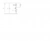
Please find the circuit attached.
I know the voltage seen across the inductor will be a triangle wave and the average voltage across it is zero volts.
Could anyone explain to me why this is so.
Thanks
p.s Vs is 15-30V, 2A
p.p.s R=0.2ohm
p.p.p.s The mosfet used is IRF511
Please find the circuit attached.
I know the voltage seen across the inductor will be a triangle wave and the average voltage across it is zero volts.
Could anyone explain to me why this is so.
Thanks
p.s Vs is 15-30V, 2A
p.p.s R=0.2ohm
p.p.p.s The mosfet used is IRF511