Continue to Site

Welcome to our site!

Electro Tech is an online community (with over 170,000 members) who enjoy talking about and building electronic circuits, projects and gadgets. To participate you need to register. Registration is free. Click here to register now.

  • Welcome to our site! Electro Tech is an online community (with over 170,000 members) who enjoy talking about and building electronic circuits, projects and gadgets. To participate you need to register. Registration is free. Click here to register now.

voltage across a diode

Status
Not open for further replies.

swordfish12

New Member
2013-03-26_102243.522.jpg
(the voltage indicated at the emitter should be 19.3 volts. )

hi everyone, i have a doubt(proabably a silly one), yet i am unable to figure it out,

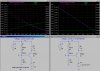
in the attached image, suppose there is no controller. And instead of a 11.5V battery at the collector of pnp transistor, we have a 0.25 ampere constant current source connected.
now assuming base current to be negligible, the emitter current is almost 0.25ampere. therefore the voltage drop across the current sense resistor(1.4 ohm) is 0.25*1.4=.35V .... now the voltage at emitter is 20-0.35=19.65 volts.

since we assumed active mode, the voltage difference between base and emitter is 0.7 volts. but we are getting 19.65-18.6= 1.05volts. but the voltage drop across a silicon diode can only be 0.7 volts.
what am i missing here. please correct if my analysis is wrong.
 
but the voltage drop across a silicon diode can only be 0.7 volts.
hi,
The above is incorrect,,,,,,,,, the voltage drop across a diode is a function of the current flowing thru the diode.. the higher the current , the higher the drop.
 
Your doubt is well founded. This is not a very good current source.

Draft48 shows the voltage across the two diodes (green), the voltage across the emitter resistor (red), the collector current (blue), and the power in the PNP (purple). Note that you must use a power transistor on a heatsink. These are plotted as a function of R2, so you can select a value that gives about 0.25A (6.8K).

Draft48a shows that it is a pretty crummy current source. R2 is fixed at 6.8K and V2 is varied from 0V to 15V to see that the current vries by 10%. Same colors as above. Forbid that we should vary the temperature....
 

Attachments

  • DF48.jpg
    DF48.jpg
    425.5 KB · Views: 165
hi,
i understood most of it..... the voltage across the diodes is changing from 1 to 1.4volts to maintain a 0.7volts across the emitter-base junction.... this can be justified by the fact R2 resistor and the diodes behave pretty much like a voltage divider circuit......what if we had a similar circuit without R2 resistor? then the voltage across the emitter-base junction will be much greater than 0.7volts.....
 
hi,
Look at this graph for a general purpose transistor.

Note the way that Vbe and Ic are related, the transistor Vbe is not fixed at 0.7V.

Which type of transistor are you using.??
 

Attachments

  • AAesp01.gif
    AAesp01.gif
    25.7 KB · Views: 162
Status
Not open for further replies.

New Articles From Microcontroller Tips

Back
Top