Continue to Site

Welcome to our site!

Electro Tech is an online community (with over 170,000 members) who enjoy talking about and building electronic circuits, projects and gadgets. To participate you need to register. Registration is free. Click here to register now.

  • Welcome to our site! Electro Tech is an online community (with over 170,000 members) who enjoy talking about and building electronic circuits, projects and gadgets. To participate you need to register. Registration is free. Click here to register now.

ViPER

Status
Not open for further replies.

Krumlink

New Member
ViPER
V
ersatile Programmable Experimental Robot

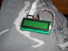
ViPER is not done as of now, but I do have The Motherboard (18F4620) and the LCD board done. I am working on finishing the Motherboard and the Motor Driver board. I had to do some repair on my LCD's Backlight, as the pins themselves were not working, so I had to make a jumper cable for it.

Picture overview and explanation:
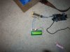
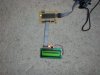
001: Overview of the entire ViPER system.

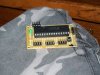
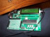
002: Motherboard, with a great picture you can read the PIC

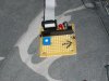
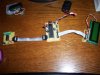
003: LCD board with pot to adjust the brightness.

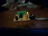
004: Fixed LCD put into socket.

005: entire system again.

More stuff soon.
 

Attachments

  • 6-4-08 001.jpg
    6-4-08 001.jpg
    500.2 KB · Views: 306
  • 6-4-08 002.jpg
    6-4-08 002.jpg
    466.9 KB · Views: 281
  • 6-4-08 003.jpg
    6-4-08 003.jpg
    467.2 KB · Views: 264
  • 6-4-08 004.jpg
    6-4-08 004.jpg
    468.5 KB · Views: 283
  • 6-4-08 005.jpg
    6-4-08 005.jpg
    531.6 KB · Views: 274
It looks good, very neat. Have you managed to get "Hello World!" on the LCD yet?

BTW, you need to learn how to resize pictures. Posting 2000x1500 pictures is not a good idea.

Mike.
 
lol oops! I have gotten a LCD to display pretty much hello world and accept a button input.
 
Oh, it has no programming in it as of yet. That is the LCD's blank startup/im on state.
 
I have been working on the Power supply and the motor board. Hope to be done by tonight or tomorrow.
 
Nice little design.I see your soldering & construction methods increasing more & more when comparing with your earlier ROBOTS.

Neatness is an requirement so you can troubleshoot them very easily.........Your new plug & play method is really nice.

Keep it up the good work.
 
Last edited:
I finished the motor board using a 100watt inverter running off a 12V18AH battery. No pics as of yet.
 
Still looking for my darn camera cable. Dunno where it is.
 
Found the USB Mini cable. My sister stole it and decided to hide it in her laptop bag. pfft.

Anyways, Here is the completed ViPER, ready for a robot.


0014: Indeed, what is Willis talking about.
006: Entire ViPER, as of now. More modules soon.
007: Newly completed Motor controller, SN754410 with caps for 5VDC and motor supplies, and one of the capacitors are orange!
 

Attachments

  • 5-29-08 014.jpg
    5-29-08 014.jpg
    475.2 KB · Views: 280
  • 6-4-08 006.jpg
    6-4-08 006.jpg
    506 KB · Views: 244
  • 6-4-08 007.jpg
    6-4-08 007.jpg
    498.5 KB · Views: 263
Status
Not open for further replies.

Latest threads

New Articles From Microcontroller Tips

Back
Top