Continue to Site

Welcome to our site!

Electro Tech is an online community (with over 170,000 members) who enjoy talking about and building electronic circuits, projects and gadgets. To participate you need to register. Registration is free. Click here to register now.

  • Welcome to our site! Electro Tech is an online community (with over 170,000 members) who enjoy talking about and building electronic circuits, projects and gadgets. To participate you need to register. Registration is free. Click here to register now.

Video Amplifier

Status
Not open for further replies.

Suraj143

Active Member
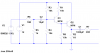
Guys this is a camera (CCTV) video amplifier.It was in a original product.

I just simulated in LT spice,but the amplitude never goes amplifies on the output.It amplifies to the same level as present in the input.

Any modifications?
 

Attachments

  • VAmp.PNG
    VAmp.PNG
    27.1 KB · Views: 232
  • Video Amp Simulate.zip
    66.8 KB · Views: 138
it has gain and it is (slightly) less than 1. that is what you should know right of the bat for common collector configuration. if you want gain greater than one, you must use either common emitter or common base configuration.
 
it has gain and it is (slightly) less than 1. that is what you should know right of the bat for common collector configuration. if you want gain greater than one, you must use either common emitter or common base configuration.

Very nice.That details really helps.
 
Ok I understood now the voltage gain is below 1 in common collector configuration.

But how it boost the video signal (quality) if it still has the same amplification as its input presents?
 
not sure i understand. you cannot boost quality, any processing ultimately distorts signal and adds noise. of course one tries to keep it low. if you want to increase amplitude of the signal, use (proper) amplifier. i've told you what is wrong with that circuit.

what kind of video signal is 50Hz? don't you mean something in MHz range?

try following:
change R3 to something bigger (39k)
change R1 to some 1k
change R8 to 220 Ohm
get rid of Q2
take output from collector of Q1...
 
take output from collector of Q1...

Sorry, but that's a REALLY silly idea :D

If you invert a video signal it won't work any more - to make a video amplifier in that way requires two transistors (one NPN and one PNP), so you can use feedback to set the gain, and provides two inversions.

However, we really need to know what he's trying to achieve?.
 
Hi thanks for the inputs.

I have a CCTV camera.Its video line is coming from 400m distance.I need to make a video amplifier & apply near DVR so it has some noticeable boost in picture quality.

I have checked with a ready made video amplifier & its working very nicely. That's the circuit I have posted.

Still my doubt is, if it has gain below 1 then how it boosts the signal...!!!
 
It may not be intended to boost the signal; only to provide a low impedance source for distribution to other circuits.
 
It may not be intended to boost the signal; only to provide a low impedance source for distribution to other circuits.

Correct - but it 'should' provide a 75 ohm impedance output (which is why such amplifiers normally have a gain of two) - and the source feeding it should already be providing that.

However, if that circuit cures his problem, then build it - it's simple enough - because it's not got a 75 ohm input impedance it doesn't need the two times gain, as this is provided by the preceding stage in the source.

Here's an example of a 'proper' simple video amplifier stage:

https://4.bp.blogspot.com/-IGps3w-a...TwHw/s400/Video_Amplifier_Circuit_Diagram.png

While googling I found this as well, which describes the process quite nicely:
 
Instead of using that very old circuit, why not use a modern video amplifier IC that provides high definition?
I used a video amplifier IC 20 years ago to feed a very clear picture from a video conferencing receiver to many TVs.
 
Instead of using that very old circuit, why not use a modern video amplifier IC that provides high definition?

Well for a start such signals are only standard definition, and such a two transistor (NPN/PNP) amplifier provides similar performance to an IC - but NOT the higher powers required to feed multiple monitors (even at 75 ohms each it soon adds up) - bearing in mind that only IC's designed for such a purpose are capable of supplying the power as well.
 
The very old circuit uses a simple emitter-follower with a high value emitter resistor so it cannot symmetrically drive the high capacitance and low impedance of a long coaxial cable. A video IC is designed to do it properly.
 
Suraj said:
I have a CCTV camera.Its video line is coming from 400m distance.I need to make a video amplifier & apply near DVR so it has some noticeable boost in picture quality.

To overcome any degradation, the amplifier should be at the INPUT of the long cable, not at its output.

This is a good quality coax cable?
It has the correct impedance (75Ohm)?
It is terminated in the correct impedance (75Ohm)?

Without ensuring these features, any discussion of amplifiers is pointless.

JimB
 
What you need is a video sender circuit. I built one years ago with the NE5539 op-amp. As said, it needs to be at the front of the cable near the source to drive the cable.
It drove 100m of cable without any issues. Getting power at that end may require a battery pack. Trying to put it at the receiving end of a cable is a waste of time.Think masthead amplifiers. They are put at the mast head for a good reason.

Due to its high gain at high frequencies, layout is an issue. I spider wired the device on copper clad board then potted the lot. Don't go too mad with the gain. You only need enough to overcome cable loss and a bit extra for good measure.
 

Attachments

  • NE5539-1.pdf
    207.6 KB · Views: 259
What you need is a video sender circuit. I built one years ago with the NE5539 op-amp. As said, it needs to be at the front of the cable near the source to drive the cable.
It drove 100m of cable without any issues. Getting power at that end may require a battery pack. Trying to put it at the receiving end of a cable is a waste of time.Think masthead amplifiers. They are put at the mast head for a good reason.

I agree, it's best at the sender end.

However, his original emitter follower circuit had a high impedance input, so is effectively giving a gain of two (because it's not acting as a voltage divider) but at the expense of correct cable matching.

Due to its high gain at high frequencies, layout is an issue. I spider wired the device on copper clad board then potted the lot. Don't go too mad with the gain. You only need enough to overcome cable loss and a bit extra for good measure.

Make it adjustable, and tweak for required result! :D
 
Status
Not open for further replies.

New Articles From Microcontroller Tips

Back
Top