Continue to Site

Welcome to our site!

Electro Tech is an online community (with over 170,000 members) who enjoy talking about and building electronic circuits, projects and gadgets. To participate you need to register. Registration is free. Click here to register now.

  • Welcome to our site! Electro Tech is an online community (with over 170,000 members) who enjoy talking about and building electronic circuits, projects and gadgets. To participate you need to register. Registration is free. Click here to register now.

Vibrator from the PIC output

Status
Not open for further replies.

disney_snoopy

New Member
hi all,
i have a problem that my PIC output connect to a vibrator and my vibrator does not vibrate when my output port of my PIC is high.
i think this is due to the current supply from my PIC not enough...

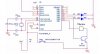
i have try to use darlington transistor but does not work.... i not sure izit my connection of my darlington transistor is correct or not...

can any1 tell me how do i need to connect my darlington transistor with my vibrator and my PIC?

or any other method to let my vibrator function?
 
Tough to guess, with no schematic, pictures, or part numbers to work from. Will probably regret asking, but there are more than one kind of vibrator in electronics, so might be a little more specific...
 
Did you build it as instructed in your other thread? Why start a new thread? (Just use 5V instead of 12V) And please don't use textspeak.
**broken link removed**
 
I've run those directly off an ATTiny13 output pin, was playing with PWM. I pretty sure a PIC is almost as good as an AVR microcontroller, but no experience with them myself. Should work okay though.
 
ya i cant find that thread... so i need to open a new thread...
ya i try this but not work also... my relay doesnt trigger... Izit i need to put the relay another power supply? or i can share with my power amplifier and PIC power supply?
 
Click on your name and choose find more posts by disney snoopy. What relay? You mentioned a buzzer not a relay.

And stop with the txt speak.
 
ya i have try it before using the relay. but not work at all..
i try to take a 4.5V battery supply and the vibrator does vibrate...
i even try to connect a power supply with 3V it also vibrate...
but when i connect it to my circuit, it doesnt work
 
this is part of my circuit... this cct i try to connect a darlington but it doesnt work.
Do comment if my connection is wrong
 

Attachments

  • cct.JPG
    cct.JPG
    34 KB · Views: 216
Well you still need a resistor on the transitors base, and you didn't build it as shown. A common 2N2222 with a 1.2K base resistor should work.
Your vibrator should not be connected to RB7 but instead use VDD.
You need resistors inline with the LEDs, 330 ohms is popular.
Is your PIC grounded? Does it have 0.1uF bypass cap on the power pins?

PS your darlington will have a higher voltage drop too.
PPS the 16F84A is an antique, use a 16F628A instead and you can avoid the crystal.
 
Last edited:
Why is your vibrator drawing power from the PIC? This completely defeats the purpose of using a transistor to switch it. Disconnect the line from the vibrator going to RB7 and connect it to the VCC line for your circuit. When you set RB6 as an output (don't forget your tris bits) and port register to 1 it will turn the vibrator on. Oh yes, as blueroom said, make sure you use a resistor to the base of the darlington, 1k should work fine.
 
Last edited:
my vibrator is connect to RB7 because the i want my vibrator to vibrate once the RB7 is high as if RB7 is low then the vibrator will not vibrate. this is the reason why i set my vibrator to RB7.

my input is RA2 and my output is RB4 to RB7. once RA2 is set to high, my RB4 to RB7 is high else is low
 
Last edited:
Why is your vibrator drawing power from the PIC? This completely defeats the purpose of using a transistor to switch it. Disconnect the line from the vibrator going to RB7 and connect it to the VCC line for your circuit. When you set RB6 as an output (don't forget your tris bits) and port register to 1 it will turn the vibrator on. Oh yes, as blueroom said, make sure you use a resistor to the base of the darlington, 1k should work fine.

Sceadwian,
i thing to confirm is the vibrator has 2 pin and izit i connect one of my vibrator pin to 5V and another pin is connect to the base with the 1k resistor?

if yes then what bout my collector of my darlington transistor?
 
Status
Not open for further replies.

Latest threads

New Articles From Microcontroller Tips

Back
Top