Continue to Site

Welcome to our site!

Electro Tech is an online community (with over 170,000 members) who enjoy talking about and building electronic circuits, projects and gadgets. To participate you need to register. Registration is free. Click here to register now.

  • Welcome to our site! Electro Tech is an online community (with over 170,000 members) who enjoy talking about and building electronic circuits, projects and gadgets. To participate you need to register. Registration is free. Click here to register now.

vga signal amplifier

Status
Not open for further replies.

lynx

Member
Hi

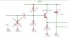
The vga output from dvb-t receiver has
been connected to a tft monitor but the display is a little bit dark..tried to fix it by raising brightness and contrast but even at 100% it's not satisfactory..

so I thought the rgb levels might not be enough...

do you think I could fix the issue by using an op-amp? if yes..do I need a high speed low noise one? and how could I implement it so I can have exactly the same amplification so I don't mess the color balance?

thanks.
 
Interesting. It should work with out the amplifier. ????
VGA can have very fast video. (DVD suggests the video rate could be 100mhz at high resolution)
This will take a fast amplifier. The gain should not be above 1.5x. The amplifier needs 75 ohm input and output impedance.
BUT
I don't have time to design this but here is a start. Needs +5 volts to run the amp. It should have the 75 ohms input but if you leave it out the signal from the computer will be higher by 2x. If that is too much gain then use 100 or 200 ohms to set the "gain".
Because the the transistor is running with a gain of 1 a slow transistor will work.
The input impedance is wrong so put this at the computer end. (so there is no or very little coax involved)
Adjust R1 for gain of 1 through 2x.
upload_2015-12-6_7-59-37.png
 
Hi

the resolution is 720p/50Hz, i'm not going to use higher than that, e.g 1080p

the 5v supply for my booster is easily available from the receiver (has hdmi port which i cannot use with the tft monitor which only has vga).

i thought I need to amplify each one if the RGB channels which should be better with op-amp meaning I need one quad op-amp or three single channel op amps

no?

also should have already measure the rgb levels before i move on building the booster, i didn't because i don't know how i can do it so i can get accurate readings...any help on that too?)
 
Last edited:
With an oscilloscope you can see the video level. The outputs of the video board are built to drive a 75 ohm load. So you should have one to ground when looking at the video. A meter will not do.

Yes you need a amp for red, green and blue. (3)

General purpose op-amps are good for 1mhz at a gain of 1 or 500khz with a gain of 2. You need 100mhz or more. That is why I chose a single transistor that will work to 200mhz with a gain of 1. Then used a impedance mismatch to get a 2x boost. I am trying to make it simple.
 
Linear Tech, Maxim, Analog Devices, and Intersil make triple video amp chips specifically for VGA/SVGA applications. There might be some that use DC control voltages to adjust the gain, a major plus in your application. Note that this type of circuit needs a pc board with a ground plane and controlled impedance traces for best performance.

ak
 
General purpose op-amps are good for 1mhz at a gain of 1 or 500khz with a gain of 2. You need 100mhz or more. That is why I chose a single transistor that will work to 200mhz with a gain of 1. Then used a impedance mismatch to get a 2x boost. I am trying to make it simple.

right...

so is your diagram complete? or it needs something more before i try it? (rgb levels i guess they must be amplified equally...is it something i need to pay special attention before building it? maybe the exact hfe of the transistors??)
 
Last edited:
Linear Tech, Maxim, Analog Devices, and Intersil make triple video amp chips specifically for VGA/SVGA applications. There might be some that use DC control voltages to adjust the gain, a major plus in your application. Note that this type of circuit needs a pc board with a ground plane and controlled impedance traces for best performance.

ak

i can build the board... though i would prefer doing it in perforated board but i guess the frequency is high enough for a perforated one, or i could try it??

Something like the LT6550 maybe in dip package.. is it suitable for what i want to do?

http://cds.linear.com/docs/en/datasheet/65501fa.pdf

probably i'll try first the way with the transistors...

P.S unfortunately i don't have a decent oscilloscope around, i own one which is about 1MHz
 
Last edited:
~43 kHz/0.3V for rgb seems reasonable measurement?
That is the sync signal in the video.
If the horizontal frequency is 43khz then the video is 1024x or 1280x + (about 20% faster) That puts the dot clock at 80mhz.
 
no.. it is certain that i'm viewing 1280 x 720, probably i'm measuring wrong because i can see varying voltages around 0.3V (not exceeding 0.6V) and varying frequency between 18-43kHz at the rgb pins relative to ground, the previous measurement comes from a multimeter with frequency meter.

it's not easy with the tools i got around to do a stable and correct measurement.

just now i thought i might be able use a video patern red or green or blue
and then measure the voltage at the rgb pins..since the multimeter appears
to be able to measure the rgb voltages (by the way what is the frequency
of these pins?)

is my thinking correct?
 
Last edited:
The "video" should be 0.714 volts peak to peak. There might be 0.3V of sync. Some video sources have sync on RGB and some only have it on Green. And VGA might not have sync in with the video at all because there are separate H and V signals.

If there is video and sync together then the 0.714 is added to the 0.3 for about 1Vp-p of signal.
A 1mHz o-scope can see the video. If you have large white areas and not much "text" the a slow scope can see fine. The "text" will probably not show well.
This voltages are measured under 75 ohm load. The voltage will be 2x with no load.

i'm viewing 1280 x 720
There are 720 lines which could be displayed at 60hz or 70 or 75 maybe 80hz. There is about 98% efficiency. (98% of the time there is video {vertically})
There are 1280 dots left to right but only 75% of the time is spent drawing horizontally.
You timing will be (60hz X 720) X 1.02= Horizontal rate.
Then (Hfrequency X 1280) X 1.25 = dot clock. (the rate at which the video is updated) I like to see the video amp work at 3X the dot clock.
 
The display is a little dark? Then the VGA signal is too strong (its amplitude is too much) or your contrast setting is too high. The DC level also affects brightness since black is a higher voltage and white is a lesser voltage.
Video has white as no signal and black is full signal. Sync is "blacker than black" and is full power.
 
or your contrast setting is too high.

no matter what i do with the contrast/brightness settings, the display is a little bit darker than it should be
so you can watch confortable, that's why i thought i should try to boost the rgb signals.

P.S how are you audioguru? nice to see you after so long time i was away from ETO. :)
 
Does VGA not use the sync pulse as a reference voltage to set the gain of the video amplifiers. If so, then the simplest solution might be to use a couple of resistors to attenuate the sync pulses.
 
VGA may or may not have sync. It does not matter. There is a time (back porch) when the video is "black". This is when black is set as a reference.
Most VGA monitors are AC coupled, so the "DC" level does not matter.
Is this a CRT monitor? (because the problem might be some where different)
Does the monitor work on another computer?
 
Yes, the back porch provides a black level, but the signal amplitude remains ambiguous because the attenuation of the connecting cable is unknown. That's why I thought that the sync pulses may provide a reference for the signal amplitude, that is unless there is a second white level reference embedded in one or more of the RGB signals.

Edit: Okay, just realized that white level is zero volts, so it doesn't need a reference. However, that still seems to indicate that amplifying the video signals is not going to accomplish anything, because the back porch will also be amplified, and the monitor's agc will correct it back down to what it would have been without the added amplification.
 
I wonder if the back light is dying.

no the monitor is fine... works ok if it is connected somewhere else.
also what i know is that vsync+hsync are two seperate pins, first time i hear what you said
about sync on rgb signals...


BobW my initial thought was about amplification!! and now we're talking about attenuation?? :p
if you think it could work somehow...give me more details on how i could use the resistors and what values i might need..
 
Status
Not open for further replies.

New Articles From Microcontroller Tips

Back
Top