Continue to Site

Welcome to our site!

Electro Tech is an online community (with over 170,000 members) who enjoy talking about and building electronic circuits, projects and gadgets. To participate you need to register. Registration is free. Click here to register now.

  • Welcome to our site! Electro Tech is an online community (with over 170,000 members) who enjoy talking about and building electronic circuits, projects and gadgets. To participate you need to register. Registration is free. Click here to register now.

Very New, need some help...polyphonic instrument?

Status
Not open for further replies.

cerupcat

New Member
Hi,

I am very new to electronic technology and building circuits. For a final project for a class I am trying to build a simple laser harp. I've seen 3-4 places online that have schematics and such to build one, but they are more advanced and also use MIDI where I need everything to be strictly analog (including sound). So no programming can be involved.

I really don't know too much about parts out there and such. Basically, right now I am trying to build the first step which is the analog sound. I followed the directions from Forrest Mims III about creating an organ, but the problem is it is not polyphonic. When two notes are active it changes both sounds.

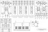
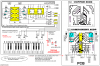
Is there a way using a 555 timer to create an organ/multi-note instrument that is polyphonic (can play multiple notes at the same time that hold out)? Or is the only way this is possible is to have separate 555 circuits for each note and have the output to each go to the same speaker(s)?

I've looked online and haven't found a schematic or anything for a analog multi-note polyphonic organ/instrument.

Thanks for any thoughts!
 
Yes, seperate oscillators is how to do it. You can, however, use a divider to create octaves from a single oscillator, so you'd need at most 12 of them. Of course these will be square waves, but you can use filtering to get a more harpy tone. A VCA and envelope would be useful to create the plucking sound and prevent the tone staying there endlessly if you don't move your finger.
 
Wow, quick response. Thank you. That makes sense although I'm not sure how the octave part works (as far as it turning on and off). Right now my goal is a major scale (7 or 8 notes), but if the octave part worked, then 12 notes/oscillators like you said would be perfect.

Are there any recommended websites for filtering the square wave? I'm assuming that I would just add parts to the oscillator. I'm not looking for necessarily a harp sound, but maybe something more attractive then the square wave. I actually would like the note held out until the beam is restored (which the oscillator should do automatically if I'm not mistaken).
 
Last edited:
Ok, well I drew up this quickly. 24 notes (2 full octaves) is easy to achieve, though I can see that a major scale may better (less chance of massive discordance!). You could do a 16 note, 2 octave major scale I guess.

You'll see a 555 oscillator, tune its frequency by varying Rtune (no lower than 1k though). To trigger it, supply a logic high input to "note trigger" on the AND gate. Its output is also shown to go through a divide by 2, formed by a D-type flip-flop. To trigger this octave down note, supply logic high to "octave down trigger". The logic outputs will come from the laser triggers once you design a suitable circuit for them.

I have shown these 2 outputs going to a summing amp. You'll have to work out correct resistor values. All the outputs (8, 16, whatever) will go into this summing amp. Notice the high octave has half the resistance, so its level will be twice as high. This is so hopefully you can use a single output filter without the level dropping on higher notes :) . The basic filter is set around 2khz, you'll probably want a better/steeper one. A high pass filter is needed too, to prevent DC at the output.
 

Attachments

  • harpy schem.GIF
    harpy schem.GIF
    5 KB · Views: 669
This is really heading towards 1960's electronic organs?.

You have 12 squarewave oscillators for your top octave, then 12 flip/flop dividers for the octave below, repeating for as many octaves as you require.

Each squarewave output is passed through a filter to give the sound you require, usually changeable for different 'voices' (and even adding higher notes for harmonics). This all runs all the time, what the keys do is simply connect the note you want to the output stage.

Later organs sometimes used a crystal and derived the top 12 note from that, but these were considered rather 'dead' sounding - the slight differences between the 12 master oscillators provided a more desirable sound.
 
You could use two hex schmitt trigger inverters to make the 12 oscillators with. You also might want to add a some trimpots to tune it with.
 
True yeah, would save a lot of space/effort. Use a regulated supply if you do though. For tuning, its probably best to tune it roughly with a pot, measure its resistance, then place a resistor a little under that value in the circuit with a small trimmer in series for fine tuning/adjustments. Or you could calculate the resistor needed and subtract a little, but I know which i'd rather do :D
 
Wow, thanks everyone. That diagram is great Dr. EM. Thanks for taking the time on that. I must admit my vocabulary is really limited. I've only built a few circuits in class (4-6 total). So I still need to do some reading on the flip/flop, the AND logic gate and also the summing amp. Unfortunately I don't have any of those parts in my kit so I can't test things out yet.

I do think I understand most of the diagram. If anyone can answer though, I'm still unsure about how notes (both octaves are triggered). How would the instrument know I want a note or play it's octave?

For example, I will have a laser pointer probably pointing at a photoresistor/phototransistor and that variable resistor will act as an on/off switch when a certain threshold is reached. I'm just not sure where (on this diagram) the on switch will go to since it looks like there are two triggers? I know if I only had a 555 oscillator that the power would go to the Vcc on the 555, but not sure on this one.
 
An IC for musical applications is the MK50240 top octave generator,
this takes a single input frecquency and divides it by various values
to produce a full octave in equally tempered scale.
The division factors are as follows:
239 -pin15
253 -pin14
268 -pin13
284 -pin12
301 -pin11
319 -pin10
338 -pin9
358 -pin8
379 -pin7
402 -pin6
426 -pin5
451 -pin4
478 -pin16
Thirteen of the pins on MK50240 are taken up by the outputs.
Of the three remaining pins, two are used for power supply connections,
and the third is the input pin.
MK50240 is very easy to use.
To produce musical tones, the clock pulses applied to pin 2, should have
a high frecquency (about 2MHz).
The outputs from the MK50240 top octave generator IC are square waves.
 
You'd have a laser and phototransistor arrangement for every note you want (though it may be possible with mirrors and optics to direct one laser onto all the phototransistors?). You need to make it so the output is a logic level change from low to high when the beam is broken. It's very easy to do with a resistor, photodiode and invertor/buffer gate :)
 
I made a polyphonic instrument having 12 oscillators for top octave,
flipflops for the octave below, and adding higher notes for
harmonics (like Nigel Goodwin refered). The instrument is easy to made,
having identically stages (attachement-poliphonic.png)
 

Attachments

  • poliphonic.png
    poliphonic.png
    33.5 KB · Views: 659
Thats cool, what did you use for the actual keys? I tried making a keyboard for my synth and it was terrible with the tactile switches :( . It would be nice to have LFO controlled modulation of the primary oscillator to get a vibrato effect when desired.
 
Wow. I'll have to study that diagram too em2006. Too be honest I don't know if I will be able to pull it off. Although it may be easy, my knowledge is really limited like I said. So i'll study that diagram and see if it looks achievable for me.

Based on the diagram it looks like I would need (6) IC 4069 and (7) 4027.

If you don't mind, I have a couple questions. Does the P1, P2, etc. mean potentiometer? It looks like there are 26 notes, is there an easy way to cut that down to 8 or 12? Obviously, 26 lasers would be too much for me. Sorry if this is a dumb question, but are the four top middle diagrams wired like the top left but using the resistor values mentioned? I'm assuming the bottom left diagram is some kind of key? And lastly, can the "audio filter" output go to a speaker instead since I don't know much about filters or wheere would a speaker be hooked up?

Thanks again for the display and i'll see if it's in my range of doing.
 
Last edited:
I believe a row of prisms will allow a laser to pass through and be directed at a right angle, meaning you could use just one laser if your careful. Whether prisms are cheaper than laser pointers is another issue, perhaps the perspex ones?
 
Dr.EM said:
I believe a row of prisms will allow a laser to pass through and be directed at a right angle, meaning you could use just one laser if your careful. Whether prisms are cheaper than laser pointers is another issue, perhaps the perspex ones?

Yeah, there are beam splitters, but it's actually cheaper to buy laser pointers (which I've already done). Plus, from my understanding, the more times a beam is split the weaker it gets. So I would need a rather expensive starting laser if I wanted to do that. Individual lasers is more than half the price. =)
 
Hi,
I hope, details and schematic diagrams from attached file (polyphonic2.png),
will help you to understand my project.

Referring to anterior schematic diagram (poliphonic.png), you understood correctly, the four top middle diagrams are wired like the top left (identically),
but using the resistor values mentioned (for tuning).

P1 and P2 are adjustable resistors and they are used for instrument tuning.
The resistors seried-connected with P1 and P2 are Very important too and serve the same scope. Please read again, what Dr.EM wrote in one of his posts: "For tuning, its probably best to tune it roughtly with a potentiometer, measure its resistance, then place a resistor a little under that value in the circuit with a small trimmer in series for fine tuning/adjustments",or respect the values mentioned by me and use 10Kohms trimmmpots(It is better to use the method described by Dr.EM).

You cannot hook a speaker directly to the output of the mentioned schematic diagram, you need to use a small audio amplifier; see the new attached schematic, which is a suggested testing arrangement.

Don't worry about the number of components, you can make only one PCB from the new schematic and test it. If everything is ok and you like the produced sounds, then you can make identical PCBs for as much tones as you need or wish.

In this project, all the sound generators are working permanently but only desired tones go to the outputs, depending on the pressed keys.

The laser commutation of signals represents the second stage of the project, and we will discuss it after you finnish first parts wich consists in the tone generating module and tuning of the instrument.
 

Attachments

  • Polyphonic2.png
    Polyphonic2.png
    51.8 KB · Views: 448
Oops!
Excuse me, I omitted an answer to your questions:
On the schematic diagram POLIPHONIC.PNG (1-st schematic),
the bottom left diagram represents LAYOUT of typical PCB 1 to 5.
It is detalied in my previous post.
The 6-th PCB (schematic top right) have a different layout.
Tell me If you need it, I'll send you in the next post.
 
Thanks you for these. I'm going to place an order for some of these parts since I don't have any of these really to be able to test this. Hopefully I can test this within the week. Time is going quickly and I have about 2.5 weeks to get something final.

So I think I understand most everything now. I only have one question in regards to the trimmpot. If I use Dr Em's method, then I wouldn't need a trimmpot correct? I would use a potenitometer in its place, measure the resistance and place that value resistor in its place. Is that correct? I've never used a "trimmer" or trimpot before so I'm still learning. Last, is there a recommended type of audio amplifier? I haven't needed one before so I don't know any.

As for the laser trigger, I believe I have that part worked out. Right now I have a light activated relay that would be hooked to the note input which will turn on when light is not falling on a photoresistor. I have a potentiometer that calibrates ambient light so it works well.


Thanks again!
 
Last edited:
Dr.EM said:
Thats cool, what did you use for the actual keys? I tried making a keyboard for my synth and it was terrible with the tactile switches :( . It would be nice to have LFO controlled modulation of the primary oscillator to get a vibrato effect when desired.

I used old relay contacts (scrap), actioned by pins fastened into the back of the keys (pushed with a hot letcon) - see attached image.

I know the LFO would be desired, but because the interferences between oscilators, caused by the distribution circuit of the LFO signal to modulated generators (CMOS gates have high impedance), i was forced to use another solution and i used tremolo effect instead. I applied this effect by amplitude modulation of the audio signal from the instrument output (6-12Hz).
 

Attachments

  • keyboard.jpg
    keyboard.jpg
    125.7 KB · Views: 367
Status
Not open for further replies.

Latest threads

Back
Top