Continue to Site

Welcome to our site!

Electro Tech is an online community (with over 170,000 members) who enjoy talking about and building electronic circuits, projects and gadgets. To participate you need to register. Registration is free. Click here to register now.

  • Welcome to our site! Electro Tech is an online community (with over 170,000 members) who enjoy talking about and building electronic circuits, projects and gadgets. To participate you need to register. Registration is free. Click here to register now.

Very Low Power Variable Resistance Switch

Status
Not open for further replies.

Dknot--

New Member
Hello,

I'm condidering to build circuit which is controlling current flowing. when resistance becomes high/low enough, it starts to pass current through.

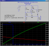
It could be something like this:

**broken link removed**

The only problem is that current consumption of the circuit should be somethng like few microamperes. The less, the better.

I have just very little understanding about electronics, and it seems impossible to find any good links about the subject. How to find suitable components, and which kind of circuit would be the best.

Also, buying some commercial, very low power modules made for this purpose would be OK.

Thanks already for your answers/comments,

-Dknot--
 
A Power NFet or PFet will control many Amps of Drain-Source current with ~1ua (gate leakage) of gate current. It is a voltage controlled device; not current-controlled like a transistor.
What are you trying to switch?

Do you care how much power the device draws AFTER it detects frost?
 
Thank you for replies!

It does not matter how much current device uses after it starts to pass current through.
1uA current drain would be great.
I would appreciate very much instructions how to build circuit with NFet/PFet.

BR,

Dknot--
 
Can you buy parts from Mouser or DigiKey? Sure would help if you put a country in when you register for this web site!
 
Last edited:
I can buy parts from Digikey and most probably from Mouser too. I would still prefer Digikey, because I'm a little familiar with that.

I am from Finland.

Dknot--
 
DigiKey has a thermistor which has ~1 megΩ at room temp, so even higher at 0degC. Coupled with a uPower CMOS OPAMP wired as a comparator, you could use that to switch the gate of an NFet. This would produce a quiescent current of a few uA. What battery do you want to use?
 
Power supply of this temperature switch-circuit would come from other "mother" circuit. Mother circuit would be initiated to ON-mode when current from +5 volt pin of mother circuit would go to reset-pin of the mother circuit. This current flow is controllerd by temperature switch-circuit. Only mother circuit is needed for power supply.

Temperature circuit that I have now in mind would start to pass current through in about 30-40C temperature. But actual temperature is not very important, I could fine tune it later.

-Dknot--
 
Here is a design based on this thermistor. Power supply is 5V. Quiescent power draw prior to switching on is less than 1uA. It has positive feedback, so it switches on with a nice snap action. I have it switching a 50mA, 5V load.

R2 models the resistance of the thermistor as a function of temperature. Note that as the thermistor cools down from 25degC toward 10degC, the circuit snaps on.

The circuit is a bit simplistic, in that it relies on the threshold voltage of the BSS123 to establish when it fires. If you build more than one, you will likely have to adjust R1 in each to get a specified trip temperature. Raising R1 reduces the trip temperature.

Ask if you dont understand something. This was simulated using LTSpice, but has not been breadboarded.
 

Attachments

  • DF40.png
    DF40.png
    40.5 KB · Views: 231
Hello Mike,

it took a while to study electronics and LTSpice. I undertand basic mechanism in your design: When Nmosfet is shut down, current starts to flow via Pmosfet. But there are still things I don't understand, even I have spend some time with your design.

Firstly, what is purpose of R6? Circuit seems to behave odd way if R6 is changed, it might not shut down or shuts down only for certain temperature range. Why is that ?

What is purpose of R5?

Why BSS123 transistor is so special, that no other transistors seems to replace it properly. Is there something to do with high ON-mode resistance RS(on) ? Why is that ?

I would apprechiate answers for those questions. Best regards,

Dknot--
 
If anyone have any clue/ andvanced guess about R5,R6 and resistance of BSS123, I would apprechiate it very much ^^

Dknot--
 
...

Firstly, what is purpose of R6? Circuit seems to behave odd way if R6 is changed, it might not shut down or shuts down only for certain temperature range. Why is that ?

R6 and R5 are a voltage divider which takes the 5V swing at the OUT node and reduces it to about 50mV. That 50mV step is added to the bottom end of the voltage divider consisting of R1 and RT (the sensor). That manifests as positive feedback (hysteresis) to the gate of M2. This is what cases the "snap-action" switching behavior. If R6 is too low, you get too much hysteresis; if it is too high, you don't get enough, and slow turn-on.

...
What is purpose of R5?

Already answered above. It is small compared to Rt, and ratio-ed against R6 to produce the appropriate amount of positive feedback.

...
Why BSS123 transistor is so special, that no other transistors seems to replace it properly. Is there something to do with high ON-mode resistance RS(on) ? Why is that ?...

The BSS123 is a N-Channel Logic Level Enhancement Mode Field Effect Transistor, which is "suited for low voltage, low current applications such as small servo motor control, power MOSFET gate drivers, and other switching applications". I set it up for high-gain, low-current by using a 100K load resistor.
 
Status
Not open for further replies.

Latest threads

New Articles From Microcontroller Tips

Back
Top