Continue to Site

Welcome to our site!

Electro Tech is an online community (with over 170,000 members) who enjoy talking about and building electronic circuits, projects and gadgets. To participate you need to register. Registration is free. Click here to register now.

  • Welcome to our site! Electro Tech is an online community (with over 170,000 members) who enjoy talking about and building electronic circuits, projects and gadgets. To participate you need to register. Registration is free. Click here to register now.

Very low power relay

Status
Not open for further replies.

TimFR

New Member
Help please

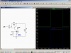
I have a very low power out put from a tractor lift sensor. +12v up & 0v down. I need to be able to operate a switch from this to enable the sat nav to know whether the lift is up or down. But the switch must only be open or closed, i.e. no voltage. The obvious answer is a relay but the 12v is very low amperage. I have try all sorts of relays, solid state and coil but they all drain too much power and don't work. The only thing that the 12V will power is a led.

Is it possible to use a simple transistor circuit to overcome this or any other ideas appreciated.
 
Have you tried connecting the relay coil between the sensor output and the +12V terminal on the same power supply as feeds the sensor?


Most sensors make an output which has a strong sink current, but a weak (or zero, if Open Collector) source current, so connecting a relay between the sensor output and power ground will not work.

In any case, a snubber diode across the relay coil (cathode pointing to the most positive voltage) will be required.
 
Last edited:
Have you tried connecting the relay coil between the sensor output and the +12V terminal on the same power supply as feeds the sensor?

That sounds like a good way to destroy the sensor, IMHO.

Hmm - just saw your (update? maybe I didn't read it close enough) comment, MikeMI - if that is true, then that may work out and be simpler than what I suggest below...

What would be best in this situation is to use a standard (not logic-level) N-channel (important!) MOSFET transistor, which usually take about 10V to turn fully on; 12V should be OK. Now, I don't know how much current that output of the sensor is able to supply, if you know that, that is good - because you want to know how much you can take, and still leave enough behind for the system it is connected to (otherwise, you'll get the relay operating, and the rest of the system won't work!). Anyhow, start by putting a resistor (1/4 watt small resistor is fine) between the output of the sensor and the gate of the MOSFET; start with 10K, if that works, leave it - if not, drop it down to 1K, etc - but don't go below 100-220 ohms. Run the drain of the transistor to ground. The source should run to the relay coil, and the other end of the coil to your battery (12 VDC, or should be). You may want to also put a snubber rectifier diode (1N4004 would be OK) across the coil of the relay to prevent voltage spikes from the collapse of the relay coil magnetic field when it is turned off from destroying the MOSFET (some MOSFETs have such protection built in, but add it anyway). Then, hook up your relay however you need to. At 0V from the sensor, the relay won't be activated; at 10-12V, it will turn on. The above is a very basic circuit (if you use a logic-level MOSFET, you can control the relay with a microcontroller - but don't do it for this circuit, you'll just waste a MOSFET); if you want a second opinion (always a good idea), look up "MOSFET relay switch" or "MOSFET relay control" - you'll see similar schematics, etc. Good luck, hope this helps!
 
Last edited:
The simple solution did not work so am going with solution 2 when all the components come.
I can only get double gate MOSFET's guess I just use one gate. They are very small can I solder to them or do I need a socket to plug them into?

Thank's Tim
 
That is the wrong sort of MOSFET. You would connect both gates together if you wanted to use them. However, double gate ones that are as small as you describe are probably too small to switch a relay.

Where are you? MOSFETs are everywhere, so you should be able to buy a selection.
 
I am in France and am able to buy from RS, could you let me know the RS reference if possible, the references for RS in France are the same as in the UK.

Thank's
Tim
 
Ups & Downs

Here is a little circuit with US Radio Shack parts. It's a single pole reed relay good for .5 amps.
 

Attachments

  • rly.PNG
    rly.PNG
    46 KB · Views: 585
Hi again
I have now the components but think I have something wrong.
In your diagram I presume the -UP is from the sensor. The sensor goes +12V on and 0V off, but very low power.
I have wired up as per your diagram but the relay is always on ie +12V at RLY. It seems the 12V is getting through the transistor what ever the state of the sensor.
 
Is the emitter of the transistor tied to +12V? Is the collector of the transistor tied to the relay coil? That should be a PNP transistor, not an NPN.

Questions about your sensor. When you say that it swings between 0V and 12V, what where you using to measure it? If a DMM, do you know what the input impedance of the meter is?

When you used the sensor to light an LED, where was the LED connected? Between the sensor output and sensor ground, or between sensor output and +12V? What resistor (if any) did you have in series with the LED? How bright was the LED?
 
Last edited:
Switch

Just to check things out, if you disconnect the sensor the transistor should be off and so should the relay. Attached is a picture of the transistor and how it should be hooked up. Is it a 2N3906?
 

Attachments

  • leads.PNG
    leads.PNG
    57.3 KB · Views: 291
Is the emitter of the transistor tied to +12V? Is the collector of the transistor tied to the relay coil? That should be a PNP transistor, not an NPN.

Yes emitter is tied to +12V & the collector to the relay coil. And yes using a PNP.


Questions about your sensor. When you say that it swings between 0V and 12V, what where you using to measure it? If a DMM, do you know what the input impedance of the meter is?

When you used the sensor to light an LED, where was the LED connected? Between the sensor output and sensor ground, or between sensor output and +12V? What resistor (if any) did you have in series with the LED? How bright was the LED?

Yes was using a DMM but I dont know what the impedance is.

The led was connected between sensor output and sensor ground, being a tractor I presume there would be a common ground, however the tractors electrical system hovers around 13.5-14.0 volts but the output from the sensor is exactly 12V. A bit too exact for a standard rectifier.
The LED was fairly bright & no resistors.

Just to check things out, if you disconnect the sensor the transistor should be off and so should the relay. Attached is a picture of the transistor and how it should be hooked up. Is it a 2N3906?

Yes using a 2N3906 a hooked up correctly as Found a picture similar to yours thanks to Google.
I'll check what happens by disconnecting the sensor tomorrow when it gets light.

I have ordered a breadboard just to rule out too much temperature when soldering.

Thank's for your help & will keep you posted.
 
Hmmm. Could be the sensor output is somehow limited to 12 volts. If so that would explain why it might not turn off. If disconnecting the sensor lets it shut off that is probably the problem as the base emitter needs to be less than .7 volts to turn the transistor off. We could add 3 or 4 1N914s in series with the input with the cathode pointing towards the sensor. Might also change the 100K to a 10K since you have extras I bet.
 
Ok, if you were able to light an LED connected between sensor out and sensor ground, with no current limiting resistor, that says that your sensor is capable of sourcing ~0.1 to 2mA from an open circuit voltage of 12V. Since the tractor's voltage bus is more positive than 12V (~13.5V), Ron's High-side switch is not a good idea. Here is what I would try:

Note that this circuit (modified Darlington) only draws 35uA from the sensor. I am modeling a 12V relay with 60 Ohm coil, which is one of the cheap automotive kind.
 

Attachments

  • DF72.png
    DF72.png
    39.6 KB · Views: 297
Just to check things out, if you disconnect the sensor the transistor should be off and so should the relay. Attached is a picture of the transistor and how it should be hooked up. Is it a 2N3906?
I'll check what happens by disconnecting the sensor tomorrow when it gets light.

Hum, with sensor disconnected the relay remains on! I will retry when the breadboard comes to make sure of things.

Note that this circuit (modified Darlington) only draws 35uA from the sensor. I am modeling a 12V relay with 60 Ohm coil, which is one of the cheap automotive kind.
I will also try this when I get some more components.

You will all realise I am not too familiar with electronics. I have a question regarding the 2 wiring diagrams you have provided. The power supply battery has +12V & -12V, QUESTION what is the down pointing triangle directly below the relay on the first diagram (earth)? Δ like this but the other way up.
 
The upside down Δ is the "ground" symbol. In the case of a tractor, it is electrically the same voltage as the metallic frame of the tractor. The battery in the tractor is likely installed such that the negative pole of the battery is connected to the frame, while the positive pole is the source which feeds all electrical appliances. Note that the battery is nominally 12V, but is actually ~12.5V with the engine stopped, and ~14V with the engine running and the charging system on. The negative pole of the battery, and the tractor frame is referred to as "ground", or 0V. The positive pole of the battery is usually referred to as "12V power bus"

When installing a new 12V powered appliance, like a radio, by default, the radio's case is electrically connected to the frame of the tractor through its mechanical mounting. This means that to supply power to the radio, only a single wire needs to be connected, and that wire would indirectly (through a switch and/or fuse) connect back to the 12V power bus.

I'm assuming that the sensor you installed is built in such that it is in an insulated case, so that no default connection to ground occurs when the case is mounted to the tractor frame, and it has three wires. If this is not so, tell us.

This means that to install the sensor, there are three wires to hook up, one that connects to the power bus through a suitable fuse, one that connects to ground (frame), and the sensor output, which connects to some external circuit.

The big question I tried to ask some time ago, is how did the maker of the sensor intend it to be connected? If you have a data sheet for the sensor, or a part number, can you post that for us to look at, and that might answer all these questions...
 
The "sensor" is pre installed by the manufacturer. The output is via a 7 pin DIN socket so the tractor can relay information to machines attached. The seven pins are, Radar speed, Wheel speed, Power take of speed, 3 point lift, 5A 12v, ground and 1 unused.

The one that I am interested in is 3 point lift. The instruction manual say it goes high(12V) on up lift and low (0v) on down lower.

I have tried using both the socket 12v and ground as well as the tractors general 12V and ground.
 
So the sensor can pre-installed by the tractor maker?

Is the 3point lift sensor a potentiometer, by any chance? This would mean that the voltage at the 3pointLift pin on your connector would vary proportionally with the position of the lift, rather than just show either 0V or 12V when the lift is raised/lowered? This might explain why the current available at the sensor output is so low.

Even if the sensor is a Pot, the NPN transitor circuit I posted should work, but the trip point will be somewhat imprecise.
 
Status
Not open for further replies.

Latest threads

Back
Top