Continue to Site

Welcome to our site!

Electro Tech is an online community (with over 170,000 members) who enjoy talking about and building electronic circuits, projects and gadgets. To participate you need to register. Registration is free. Click here to register now.

  • Welcome to our site! Electro Tech is an online community (with over 170,000 members) who enjoy talking about and building electronic circuits, projects and gadgets. To participate you need to register. Registration is free. Click here to register now.

Very Confused and Need Help

Status
Not open for further replies.

Ben Damann

New Member
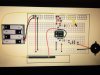
I'm trying to construct a sort of instrument that can play things I draw in pencil. I've included a picture of the protoboard setup. The output to the speaker is a square sine. But for the purpose it's being constructed for, I really need a sawtooth coming out. I've toyed around with some different ideas, but don't really know what I'm doing. Also, I need the sawtooth wave to vary in pitch just as the square would when I change the resistance in the circuit by touching the graphite strip in different locations.

Any help is very, very greatly appreciated.
 

Attachments

  • 555 Instrument.jpg
    555 Instrument.jpg
    1.9 MB · Views: 215
The output to the speaker is a square sine.

It's either a square wave or sine wave. It can't be both, however you can create a complex wave by using multiple waveform types and mixing them together.

Also, I need the sawtooth wave to vary in pitch just as the square would when I change the resistance in the circuit by touching the graphite strip in different locations.

The "pitch" change is caused by varying the resistance (your graphite strip) that the 555 timer is seeing, thereby causing the output "frequency" of the oscillator to change.

If you need a sawtooth wave form, derived from your square wave, (although I don't think your speaker will like it much) you need to add a thing called an integrator. Depending on how linear you require the output to be, you could simply add a small capacitor, a transistor and a couple of biasing resistors to form a little switch and use that to discharge another small capacitor that is charged via a resistor. Both of these components being in series across your supply, with the transistor collector connected to both where they join in the middle. You still vary the "pitch" or frequency as you are doing now, and the output of the integrator should follow along happily. You can play with the charge resistor value and the discharge capacitor value until you see, or in this case, hear the waveform you're happy with.

Do a giggle search on simple integrator, there must be countless examples and descriptions out there :)
 
I think I follow what you're saying. I'll post a schematic in this thread with what I think is going on within the next day or so. Thanks!
 
In case I wasn't clear, you feed the small capacitor before your transistor with the square wave output that you have now on pin 3 of your 555 timer :)
 
It might not work but try it, unplug the resistor from pin3 and plug it int pin2, that if it doesnt stop the oscillator will give you a trinagle wave, not sawtooth but closer than square.
 
The sketch shows a piezo squeaker, not a loudspeaker. The piezo squeaker will probably squeak the same if the signal is a sawtooth or a squarewave.
 
The sketch does show a piezo, but driving it with a sawtooth ain't gonna sound all that great, and probably a lot worse if he then later swaps it for a real speaker. Apart from that, he's unlikely to get much oomph out of it driving it with a sawtooth, probably better sticking with the square wave if a piezo is all he's gonna be using :)
 
The idea is to eventually run it out through a TRS into some stomp boxes, then into some larger speakers in a recital hall.
 
Driving speakers at high power levels with a square wave means driving the speaker cones from one extreme of travel to the other in an instant. Which is not very good for the speaker at all. Driving it with a sawtooth will have a similar result, but will drive the cones one ended, not only sounding terrible, but just as likely to damage your speakers as driving them with a square wave. Speakers are designed to run from sine waves and will be happiest when fed those :)
 
That's good information to have. So I guess my question has changed then. How could I convert that square into a sine wave?
 
Ok, so now we are getting into filtering territory. You will need a low pass filter of some sort to convert your square wave to a sine wave. As an aside, if you were to build a 3 pole filter, at each pole of the filter, you will have something approximating a squashed sawtooth waveform, a triangular wave form and finally a sine wave form, all derived from your original square waveform. You will lose some of your signal amplitude by passing through the filter and will likely have to compensate for that following the filter to restore your original amplitude level. Giggle is your friend, there are hundreds if not thousands of good worked examples, demonstrations and freely available filter design calculators on the web :)

I should say that I'm referring to a passive filter here, i.e one without any kind of active element. You can also build an active filter to achieve the same thing but also add gain at the same time to restore your original signal amplitude without any additional gain stage being required, however it is a little more involved than simply tossing a few capacitors and resistors together :)
 
Forget the 555 and search for some Sine wave Oscillator Circuits.
 
That would mean the op would need to throw out his original design, which seems to be working well as a basis for his plan. I agree though that a good colpitts design with bias stage and varactor type control would probably be a better design, it's just not so easy for a newcomer to achieve reliable startup etc. You must admit though, that the venerable 555 is about as newbie proof as it gets, unless you get it totally whacked, it's hard to stop it oscillating! So until the op is comfortable rolling his own oscillator from the ground up, I think it's best he stick with tried and tested building blocks that there are loads of easy peasey tutorials for on the web. Perhaps rolling his own oscillator design will be a mark II project :)
 
If the 555 circuit is working correctly, and you can vary it the way you want, and the only problem is that its output is a square wave rather than a triangle or sawtooth wave, take the output from pin 2/6, the top of the timing capacitor. This has a modified triangle wave on it and its amplitude is a constant regardless of frequency. However, this is not a low impedance output like pin 3 is and it is not as loud. Connect it to you amplifier input and see what you think of the sound.

A pure triangle wave has twice as many harmonics as a square wave, but they drop off in amplitude more quickly as the harmonic frequency increases.

ak
 
A speaker is not designed to play only sine waves that sound like a flute. Speakers can play any waveform but a woofer cannot play high frequency harmonics and a tweeter cannot play bass sounds.

Your 555 will sound like a buzzer or a beeper since it will simply be on or off. It cannot have the dynamics (rise and fall times) of a musical instrument.
 
Status
Not open for further replies.

Latest threads

Back
Top