Continue to Site

Welcome to our site!

Electro Tech is an online community (with over 170,000 members) who enjoy talking about and building electronic circuits, projects and gadgets. To participate you need to register. Registration is free. Click here to register now.

  • Welcome to our site! Electro Tech is an online community (with over 170,000 members) who enjoy talking about and building electronic circuits, projects and gadgets. To participate you need to register. Registration is free. Click here to register now.

Velleman MK111 - help!!!

Status
Not open for further replies.

Skimask

New Member
Hi Folks,
I'm a newby to this forum and a complete idiot when it comes to electronics :confused:
I require an LED to come on for around 8 seconds or so and switch off.
I bought the velleman MK111 kit - and as my soldering skills are non-existant. asked my mate to make it up for me.
It works fine - I just wired in my LED to where the contacts (?) for the onboard LED are located.
Unfortunately it does come on for the required time and switches off. What I didn't want is it to come back on again through the pulse variable resistor (rheostat?).
I unsoldered the pulse rheostat and now it switches on and stays on:mad:
Is there a fix for this please? I thought if I gathered some resistors and joined them in series to give a high resistance and put them in place of the pulse resistor the pulse or delay would occur after a long time - by that I mean after an hour or so! If this is the correct solution, where would I solder in the ends of the resistors on the circuit board?
Sorry about the long winded post and hope the post makes sense!!
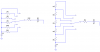
I'll try and attach the schematics PDF.View attachment manual_mk111.pdf
 
The 555 timer integrated circuit in that kit can't time for more than a few minutes. A completely different circuit is needed for a time of 1 hour.
 
Do you really want it on again in 1 hour? As audioguru stated, the 555 cannot time that long.
Or do you just want the LED to come on for 8 seconds after applying power and NOT come again until the power is turned off and on again? If so, then the circuit you have is not designed to do that, but you could modify it to do so.
 
Hi Folks, thanks for the prompt response! KChristie, you are correct, I do want the LED to come on once, until the power is turned off and on again!
How could it be modified to do so?
Thanks
Adrian
 
Make the mods as marked in red on the diagram below:
 

Attachments

  • timer.gif
    timer.gif
    9.3 KB · Views: 2,770
Hi Kchriste,
Many thanks the kit is now working as it should thanks to your modifications!!
When modified it only gave a pulse of 6 secs. But once the variable resisitors were swapped over it gave a longer pulse - although it has a coarse adjustment.

Cheers
Adrian
 
Skimask said:
Hi Kchriste,
Many thanks the kit is now working as it should thanks to your modifications!!
When modified it only gave a pulse of 6 secs. But once the variable resisitors were swapped over it gave a longer pulse - although it has a coarse adjustment.

Cheers
Adrian
If you want better control over the delay, restore R2 to 47k, and change R1 to around 33k. You could get even finer control, but you probably don't need it. (?)
 
The MK111 is almost perfect for a project I'm working on except I need a 30 minute to an hour pause. Does anyone know of an interval timer with a longer pause control or can the MK111 be modified? I looked at the Altronix 6062 but I don't see that it automatically resets (interval) without an external trigger. TIA
 
Hi
I was also searching for a modification which allows for an increased pause time. The 5 second max pulse time is fine for my purpose.
I came across this mk111 mod which seems ideal as it provides a pause time of upto 30 minutes. I`m not sure if it also alters the pulse time range in the process though.
The component changes are marked in blue on the attached schematic,but would it do the trick? ;)

**broken link removed**

Cheers
The maximum pulse time is about 3.5 seconds, and the pause time with perfect capacitors should be over 30 minutes, but capacitor leakage could reduce that to as little as 20 minutes. You would have to try it.
 
Hi Ron
Thanks for the reply.
20 minutes of pause is a useful amount, the pulse time is a little short though.
Is the value of RV2 responsible solely for the pulse range or does it also affect the pause range? I guess the latter as the former would be far too easy ;)

Thanks again
Best Regards
Colin
 
Hi Ron
Thanks for the reply.
20 minutes of pause is a useful amount, the pulse time is a little short though.
Is the value of RV2 responsible solely for the pulse range or does it also affect the pause range? I guess the latter as the former would be far too easy ;)

Thanks again
Best Regards
Colin
Actually, they should be totally independent, with no interaction from either control.:)
 
Last edited:
Hi Ron
Thanks,thats good to know :)
Presumably then, i could play around with the value of VR2 to alter the pulse duration too?
If 47K provides a 5 second pulse and 22k is 3.5 seconds, would increasing the value of VR2 by ~25k equate to adding +1.5 seconds to the pulse duration or is it not linear?
If it is a relatively fixed value, i could replace VR2 with a 12 way rotary switch to add series resistors for a switch selectable Pause duration.
Switchable steps would make it easier to locate the same setting twice than on a fairly coarse preset.
The series resistor tolerances may add a twist or two ;)

Best Regards
Colin
Pulse width is linearly related to resistor value. Below are two ways to use a switch (I only show 6 poles). The resistors on the left are independent of each other. The ones on the left add.

EDIT: The Spice model for LM555 is inaccurate, in that its output voltage swings to the positive rail, while a real LM555 swings to about 1.2 to 1.4V below the positive rail. I re-ran the simulation with that correction, and the pulse width was 5 seconds, as opposed to 3.5 seconds, which I stated earlier.
If you are using a CMOS 555, 3.5 seconds is about what you'll get.
 

Attachments

  • timing switch.PNG
    timing switch.PNG
    16.9 KB · Views: 563
Last edited:
Thanks Ron, i appreciate the info.
I`ll probably use series resistors on the rotary that add. That way i can use the same value although either way is easy enough.

Do these values sound reasonable as a starting point if i omitted C4 from the circuit?
3MΩ + (11x) 470KΩ series on rotary for a range of ~4-10 mins Pause.
47KΩ + (11x) 47KΩ series on rotary for a range of ~3-40 seconds Pulse.

Best Regards
Colin
I ran some sims on these ranges. Based on it, the values came out as follows:

3.3M + (11x) 3.3M pause
39k + (11x) 47k pulse

HOWEVER: The model apparently has 1GΩ (1000MΩ) input resistance on pins 2 and 6, as evidenced by the current into these pins in the simulation. I don't think these exist in hardware. The bottom line is, with resistors greater than 10Meg, combined with electrolytic (leaky) capacitors, the models aren't too good at accurately predicting timing results. You may have to experiment to get what you want.
 
Hi Ron
Thanks again.
I have a couple of mk111 kits on order. When they arrive i`ll try out the various resistor combinations and see what happens.
I`ll post the results here so they are available as a reference.

Best Regards
Colin
 
Hi Ron and all,
Sorry for the delay in posting the results of the timer mods..the kits took 4 weeks to arrive!
Anyway,I finally have both timers built and working. Here are the results as promised, in case they are useful for future reference.

I only replaced the presets with 12 way rotary switches and series resistors, everything else is the standard kit.
The first timer has a pulse range of 1-12 seconds in roughly 1 second steps and a pause range from 30 seconds to 3mins 30 seconds in roughly 15 second steps. I had to play around with the resistor values to get close to the timing i needed.
I ended up using 3x 22k resistors in parallel (~7K) for each switch position on the Pulse rotary. The Pause rotary used a 470k resistor on position 1 with 220k resistors on the rest, this resulted in a 34 second pause on the 1st switch position with roughly 15 second increases for the others.
I also tested 330k resistors but they gave a step of around 24 seconds..a little too much.

The second timer has exactly the same pulse values (roughly 1-12 seconds) but i increased the pause step to 30 seconds by using 470K resistors throughout. It turned out to be reasonably close with a 6 minute 30 second maximum pause on switch position 12.

Best Regards
Colin
 
Status
Not open for further replies.

Latest threads

New Articles From Microcontroller Tips

Back
Top