Continue to Site

Welcome to our site!

Electro Tech is an online community (with over 170,000 members) who enjoy talking about and building electronic circuits, projects and gadgets. To participate you need to register. Registration is free. Click here to register now.

  • Welcome to our site! Electro Tech is an online community (with over 170,000 members) who enjoy talking about and building electronic circuits, projects and gadgets. To participate you need to register. Registration is free. Click here to register now.

Varying current

Status
Not open for further replies.

Gregory

Member
I have a power supply That supply 37 v DC ( battery pack ) and a current of 9 amps I wish to vary the current but not using resistors . Using a pot . Can anyone supply me a circuit that I can adapt to my power supply to vary current.
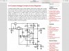
I am driving 10 strings of 8 LEDs require 36 volt 7 Amps I do not want to adjust the voltage. I require to dim the LEDs
 
What you need is a constant-current LED driver; not a constant-voltage power pack with a bandaid stuck on it.
 
That still won't allow the OP to vary the current. What is required is to PWM the LEDs. Google something like "pwm led mosfet schematic" and see what turns up.

Mike.
 
Use a Buckboost converter.....you don't have enough headroom for a buck.
You could use say a lm3421 for each string.
Or you could use one of the linear ics.....eg lt8705..that can do buck and boost and could proably do the entire 9 amps from one chip. (its synchronous)
Or split them into smaller strings and use loads of ZXLD1360's for a simple solution.
bUCKS ARE EASIER THAN BUCKBOOSTS BUT NEED HEADROOM...YOU COULD SPLIT YOUR STRINGS UP A BIT TO GIVE YOU THE VOLTAGE HEADROOM SO YOU CAN USE A BUCK...THEN YOU COULD USE EG LOADS OF ZXLD1360'S IN PARALLEL.
(sorry about capitals)
zxld1370 HAS A GOOD APP NOTE TOO FOR DRIVING LEDS...AS I SAID, JUST PUT LOADS IN PARALLEL IF ITS TOO MUCH CURRENT FOR ONE STAGE.
or use a linear.com chip which does a synchronous buck converter, say.

So if you are a beginner I would say use a buck converter, and split your leds up so that you can just drive them all from a buck.(s)
These chips have ports which will accept an anlog signal from a pot to adjust the led current.
diodes.com website will show you.
HV9910B also does a real simple buck in constant off time....again put 'em in parallel.
 
" image.jpg image.jpg image.jpg
image.jpg
image.jpg
image.jpg
image.jpg image.jpg image.jpg This. Is a photo of the led I am using .
Is this the circuit you are indicating.
I thank you for your on going help as I have run into several problems with. This led
I am working on a under water light for photogeoge
 
Last edited:
lt8705 is la crem de la crem.
You don't absolutely have to use it.
Its just that you don't appear to have enough headroom above your led bank voltage for a simple buck.
A simple boost followed by a simple buck is another way round it.
 
The LT8705 is a boost/buck that could work for what you want to do. It is a little complicated.
 

Attachments

  • LT8705_Ad_Final(P).pdf
    692.6 KB · Views: 246
you are supplying a bank of 8 strings of 10_leds_in_series from 37V.
I see the strings cannot be supplied individually, as the top anodes are all on the same node.
Its 7 amps, so you need a synchronous converter i'd say, or a big heatsink on the diode if not.
So its either synchronous buckboost, the only controller I can currently think of for that is the lt8705.
..or a synchronous boost followed by a synchronous buck. (the sync boost being voltage regulated, the sync buck current regulated.)

..or of course if you didn't want to go synchronous, then a couple of paralleled current regulated sepic converters would do it, say 3 or 4 of them.
..unless you don't have size constraints you could just use through hole components, heatsinks and do the job with one sepic....id do it uncoupled...remember the LLC resonant frequency shouldn't be near the feedback loop frequency of the sepic....also the ripple on the sepic cap should be <5%, also the sepic cap needs a rc snubber across it, r=rt(L/C) where L = the sum of the two L's. Remember that the fet and diode currents will be exactly the same as they would be with a 1:1 flyback with the LPRI and LSEC being half the value of your individual inductors as you use in the incoupled sepic version.
 
Last edited:
image.jpg image.jpg This is what I am using at present but If the pot is turned to far then the current destroy the led light.
I need to limit the current to 7 amps max
This is why I want a current adjustement not a voltage adjustement but I would like to use a pot not resistors to step the current. Hope this can help you to help me. There is no problem with heat sink as the housing is aliminum and the unit is in water all the time when being used. image.jpg
 

Attachments

  • image.jpg
    image.jpg
    1.3 MB · Views: 236
Last edited:
in that case just use a current regulator comprising a big transistor with its base being driven by an opamp with negative feedback. The opamp should have a reference into it, the voltage on same should be as the voltage you want across your sense resistor.
You change the current by twiddling a pot to adjust the reference into the one pin of the opamp.
There will be loads of these on the web.
Search eg...
Linear led current regulator
Opamp based linear led current regulator
Discrete linear led current regulator
 
I have attached a circuit digram of what I think is what you are talking about.
If this is not correct could you help me out.
Are there kits available for this application.
I supply 38 volts input and require 36 v output at 8 amps max the amps being variable
 

Attachments

  • image.jpg
    image.jpg
    517.6 KB · Views: 224
You need a "low dropout regulator" LDO... I don't believe that your headroom is enough for even a linear regulator, especially at that current..i think you need a switcher.
sorry I forgot how low your vin was in relation to your vout....2v headroom is not enough I don't believe
 
That still won't allow the OP to vary the current. What is required is to PWM the LEDs. Google something like "pwm led mosfet schematic" and see what turns up.

Mike.
How has this post gone unnoticed? Seriously...this is what you need to do.

And you can always just buy a simple 0.1ohm or 0.2ohm 15W resistor in line to drop that extra volt even when at max current.
 
good point,
Just make sure that the lowest forward voltage of the led bank (which would be at highest temperature) doesn't result in too much power dissipation in whatever resistors you choose
 
The current is the problem I need to reduce the current will the 0.2 ohm 15 w resistor in series be enough to drop the current 2 amps as I keep destroying the led lightes.
Thank you
 
right, I see your point.....when we just said that you could do it with a series resistor and PWM the leds, we were forgetting that the led string voltage is not a constant, it varies with temperature, and as it varies the resistor value would need to vary...so its a no-go'er.
I think you are going to have to do a buckboost converter.
That's a switching led driver.
Do you understand about switchers?..eg V=Ldi/dt , Vout/Vin = D/(1-D) for bukboost, D = t(On).T(sw),
Trapezoid waveform equations.. etc etc?
 
Status
Not open for further replies.

Latest threads

New Articles From Microcontroller Tips

Back
Top