Continue to Site

Welcome to our site!

Electro Tech is an online community (with over 170,000 members) who enjoy talking about and building electronic circuits, projects and gadgets. To participate you need to register. Registration is free. Click here to register now.

  • Welcome to our site! Electro Tech is an online community (with over 170,000 members) who enjoy talking about and building electronic circuits, projects and gadgets. To participate you need to register. Registration is free. Click here to register now.

Variable Voltage Current Amplifier

Status
Not open for further replies.

wuchy143

Member
Hi All,

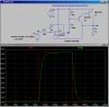
I have a variable voltage amplifier which takes in 0-5v and outputs ~6.1V - 10.2V depending on the 0-5v input. I've simmed it. It works and I"m happy with it. For example you input 0 volts you get 6.1 volts out of the circuit. Or if you input 5v you get 10.2 volts out of the circuit. It's a linear relationship.

I would like to be able to provide more current than my amplifier can handle but still keep the same voltage swings. I'd like to drive 250mA maximum for my variable 6.1v - 10.2 volt signal.

I've never done a circuit like this and upon searching I see a darling ton pair might work for me. Thing is how do I keep my voltages to stay the same? There are also chips I could just, "buy" and they will do what I want but I want to try and find a more creative way of doing it and perhaps cheaper.

Any thoughts or ideas I could try?

Attached is what I have so far.
 

Attachments

  • Untitled.jpg
    Untitled.jpg
    177.5 KB · Views: 167
hi wuchy,
You connect the Darlington transistor inside the feedback loop of the OPA.

Eric

Post your LTS asc file and details of your OPA
 
I'm using LM324 for my OPA.

I'm going to take a look now at putting the dpair where you mention above.

Thanks!!
 

Attachments

  • +9v_bl_out.asc
    2 KB · Views: 130
As Eric mentions, make sure that the transistor is inside the feedback loop.

And then remember that because of the base emitter drop, the maximum output will be about 1.5 volts lower. Since a LM324 only swings approximately to Vsupply - 3 volts, the compound will only swing to Vsupply - 4.5 volts.
For the required 10.2 volt output, your supply must be at least 14.7 volt......make it 15 V.
 
Thanks Schmitt,

I only have +12v available to me which can swing +-1/4V. Hmm looks like I need to re-think my topology.

LM386?
 
Last edited:
hi,
Here is the LM324 sub, asy and your asc modified.

Place the sub in the LTS lib/sub folder and the asy in the lib/sym folder

The ZTX out is for demo only

E
 

Attachments

  • wuch1.zip
    2.7 KB · Views: 128
A PNP darlington emitter follower can pull down but not pull up. Since your load is connected to ground then you must use an NPN darlington emitter follower to pull up and a 13.5V supply.

An LM386 has an output voltage drop of about 2V when its load resistance is 16 ohms so with a 12V supply and a 40 ohm load (250mA peak) the output might not reach +10.2V.
 
Here is how to use a PNP Darlington to drive a ground-referenced load. Note how the output of the opamp stays where a LM324/358 can drive to. Also note that it will pull within a volt of the positive supply rail. This power amp has a gain of 1, so do your offsetting in the first stage..
The X-axis in the plot is input voltage. Note everything is linear until the output reaches 11V.

After posting this, it occurred to me to check the transient response. With the extra inversion inside the feedback loop, it wasn't stable, so I added the secondary ac feedback. The transient step response can be tweaked with the feedback capacitor.
 

Attachments

  • DF52.jpg
    DF52.jpg
    223 KB · Views: 178
  • DF52a.jpg
    DF52a.jpg
    195 KB · Views: 177
Last edited:
Status
Not open for further replies.

Latest threads

New Articles From Microcontroller Tips

Back
Top