Continue to Site

Welcome to our site!

Electro Tech is an online community (with over 170,000 members) who enjoy talking about and building electronic circuits, projects and gadgets. To participate you need to register. Registration is free. Click here to register now.

  • Welcome to our site! Electro Tech is an online community (with over 170,000 members) who enjoy talking about and building electronic circuits, projects and gadgets. To participate you need to register. Registration is free. Click here to register now.

Variable PIC controlled resistance

Status
Not open for further replies.

Huttojb1

Member
Hi all,

not been on here for a while, I have picked my project up recently and actually stuck on the same issue I had previously.

I have a analogue gauge that outputs (on a needle) a value dependable on resistance. When I connect the gauge signal pin to the resistance box and reference on ground I get a range of vales from 10ohms to 240ohms.

240 ohms gives me 0
216 ohms gives me 20
176 ohms gives me 40
153 ohms gives me 50
124 ohms gives me 60
92 ohms gives me 70
60 ohms gives me 80
40 ohms gives me 90
10 ohms gives me 100

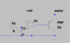
I would like to control the value via a PIC, I sure I got this working before when I put a transistor across a 240ohms resistor and PWMed the Transistor to ground. But this is not working. Is there another way?

thank you in advance and stay safe all

Jason
 
What is the supply voltage to the gauge?
Can you post a link to the type of gauge or its specification? Is it a vehicle fuel gauge?
 
Last edited:
Hey Alec_t

I’m speaking to you on


So gonna let the discussion happen on that forum, I only use these 2 forums so posted on both for the maximum help.

Jason
 
What is the current going through the resistor(s)? Is there a constant voltage across the resistors? Just trying to learn more.
 
Hey RonSimpson

I have also posted the issue here aswell


But yes, I have added the voltage across the resistor values, I have Alec_t helping but any advise I’ll surely take on board.

I’m also looking for solutions whilst I’m waiting, and thought of a resistor ladder switching by a bit shifter (as I haven’t got many output pins left on my micro)
But I am unable to work out what values i would need to have a 8pin shifter with 8 resistors in parallel and be able to make up resistance between 10ohms-240ohms.

But like I said, I do have some helpful forum member helping me and hopefully will provide something shortly, but if you have an idea, advise or solution to my idea above... I’ll be all ears.

100%. > 10ohms. > 0.728V
75%. > 60ohms. >. 2.474V
50%. > 140ohms. > 3.411V
25%. > 200ohms > 3.729V
0%. >. 240ohms > 3.870V

these are the major ticks, what ever solution I use, I would like as much resolution as possible.
Jason
 
What PIC are you using?
---------
Some PICs have a analog outputs. Some compilers will help you set up a PWM in a pin. You might have to add a DAC IC to the project. Either way I am looking for a 0 to 5V analog output.

So if you PIC causes a voltage at R1 the opamp will make that voltage at "meter" and force the meter to move. My guess is that forcing the voltage will get you the same results as applying a resistance. (apply 2.4V gets you 75%) Because the meter pulls some power the transistor and amp are needed.
1591482019967.png

OPAMP needs to be one that works well at 5V supply. Probably R-R input and R-R output. (do not use the AD712)
 

Attachments

  • 1591480106886.png
    1591480106886.png
    10.9 KB · Views: 164
Thank you Rob for the advise. Unfortunately I don’t have a analog o/p; I’m using a PIC18F4680.
Currently I’m not looking to change or upgrade my PIC yet, something I will look at in the future but there has been a 7 year project window for this and I’m just trying to get it finished now.
i actually don’t have a PWM Pin spare as I use this for something else, currently I’m bit-banging the pin to get my PWNfor the transistor

I’ll try and set up the circuit on veroboard to see what the output is, I can bitbang the pin with a cap giving me the 0V-5V. I do not need a fast response time, I’m talking this can be 10 seconds plus.

thank you and it be on the list of attempts.
Jason.
 
Ps, would you recommend OpAmp AD8603AUJZ-REEL7?
 
OK, I have an idea, Not sure if this would work but I was looking at this last night, would like to run this idea past you aswell.

I have 3 digital pins I can use on the micro, an I have used this configuration before, not for this purpose, but I think this will work.. please advise?

This is the Bit Shifter cct I'm thinking about with a selection of known resistor values. I can select the resistive path by the bit shifter.
Attcahed - BitShifter Resistor Select.png

I have also attached the 'make-up' of outputs to drive high to select certain conditions. Altgough I missing a few, I have got the major values, and I think if I mess around alittle more I could get the values I need.

Please advise?
 

Attachments

  • BitShifter Resistor Select.png
    BitShifter Resistor Select.png
    122.7 KB · Views: 317
  • Fuel Sender Idea.png
    Fuel Sender Idea.png
    47 KB · Views: 149
You would get better resolution using a binary- or logarithmic-value resistor set; eg. each resistor something like 1.5 or 2x (2/3 or half) the value of the ones either side of it. Also add one another step higher than the highest switched one, permanently connected.

Switching combinations of those in then give you a wide range of fine changes, rather than just a few divisions of 270 Ohms.
Using eight outputs and eight scaled resistors plus the permanent one give 256 unique values.

eg. 10, 22, 39, 82, 150, 270, 470, 1K + 1k8 permanent should give a decent range, if not absolutely linear.


edit - ps. Looking at your circuit again; if you need more than eight extra output bits, just feed the next shift register input from the serial output of the preceding one (pin 9 for the 595), and parallel the clock & latch pins.

Then send 16 (or 24 or however many bits) before sensing the latch pulse to transfer everything to the outputs.
 
Last edited:
Sorry, I forgot to transfer the values, this is one of the solutons, I have a really helpful gentlemen thats offered another solution on the other forum with alot lett footprint. But this is something I understood. See new Attachment.
 

Attachments

  • BitShifter Resistor Select.png
    BitShifter Resistor Select.png
    124 KB · Views: 156
I estimate that the sensor unit provides current to the sense resistor from a 4.76112 volt source via a 55.4 ohm resistor. This is calculated from the readings in post #5 I calculated this using the 0% and 100% values in post #5 From this we could do a calculation in the PIC to convert percentage values to a resistance value and use that to select a combination of 8 binary related resistors in parallel. The resistors could selected using mosfets. An alternative would be to control the drive to a mosfet (Behaving as "the resistor") to give the calculated voltage across it. There is some sample code to do the maths in assembler on the Microchip website. (I have used those routines to do the calculates needed to read the output from a BMP280 sensor using a PIC12F1840.)

Les.
 
Les, Thank you for your input.

Just to pair the 2 post concerning this please look at :
I think your suggestion of using a MOSFET as a resistor is the solution Alec_t has come up with in Post #12 (link above)

Like to thank you all, I have now 3 solutions I want to try, mine being the most primitive and most footprint so this is not ideal. The other 2 solutions provided by Ron Simpson in Post #6 Above and Alec in Post #12 on the link gives me a way forward.

I'm ordering the parts today and these should arrive on Tuesday and then I can give it ago. I will try and bit bang my Pin to provide a PWM at 1khz and vary the duty cycle to see if this is possible; cannot see why not!

thank you again.
 
I estimate that the sensor unit provides current to the sense resistor from a 4.76112 volt source via a 55.4 ohm resistor.
I used two others of the post #5 values and got 4.75V and 53.8 Ohms. So we agree on what's inside the gauge :).
 
Status
Not open for further replies.

Latest threads

New Articles From Microcontroller Tips

Back
Top