Continue to Site

Welcome to our site!

Electro Tech is an online community (with over 170,000 members) who enjoy talking about and building electronic circuits, projects and gadgets. To participate you need to register. Registration is free. Click here to register now.

  • Welcome to our site! Electro Tech is an online community (with over 170,000 members) who enjoy talking about and building electronic circuits, projects and gadgets. To participate you need to register. Registration is free. Click here to register now.

variable constant current designs.

Status
Not open for further replies.

kybert

New Member
Hi,

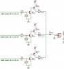
I need a variable current source that can provide the following constant currents:

2.8mA
16.8mA
42.8mA

Each can vary slightly if required. Its for a batt charger, so each current must be switched on/off via a processor.

I dont want to use a IC, too expencive, so looking for a solution using descrite devices.

I have a 3.6v NiMH @ 280mA, so the above relates to 0.01C, 0.06C and 0.5C charging rates.

I've got the code ready to charge the battery, detect peak etc... but no matter what i try, i cannot design the constant current generators.

The avaliable supply voltage is 15VDC.


Please someone suggest somthing, been working on this section of the project for too long now, and i just want to move on!!


Joe
 
An opamp set up as a current source would be the easiest. In this setup the current through a resistor is used to generate the feedback signal. You might need a driver transistor for the 42.8mA but thats not too hard. You can use a PWM signal generated by the processor to create the setpoint voltage.

This circuit is close to what you want. Git rid of RL and IL and replace RF2 with the battery. The voltage at Vz sets the output current I = Vz/RF1
 

Attachments

  • curentdriver.gif
    curentdriver.gif
    2.7 KB · Views: 975
Yep, i can handle that.

Whats the votage drops assumed accross the transistors for this circuit, since the closest value for 232R is 240R so i need to mod the voltages a bit / calc. power in R etc..


Joe
 
Yes, also good, except i have 5V form the micro and 15V from the main supply.


And i wish i have simulation s/w too..


Joe
 
OK, can someone with a simulator please simulate the attached pic to ensure that im getting the correct current through the battery?

The 3 enable lines at the top are only enabled one at a time, by a processor (5v logic). The lower enable is a fail safem, and enables/disables the current sources.

They are supposed to be constant current sources. The supply is 15VDC, and the battery is 3.6V.

Note that Q3 and Q4 are BC337s to allow for the higher currents (180mA).

I've writtin on different voltages around the circuit. Not 100% sure that they are correct though!

All components are real values, i.e. the resistor values can actually be bought cheeply.

Cheers.


joe
 

Attachments

  • attempt1.jpg
    attempt1.jpg
    22.1 KB · Views: 867
Get rid of R1, R2 and R3, or, if you feel insecure without base resistors, make them each 47 ohms. Change R4 to 1.5k, R5 to 240, and R6 to 30. These values get you closest to your required currents using standard 5%values, according to SwitcherCAD III simulation.
 
Hi,

I made a big mistake in the original post. I need to charge the battery incircuit, so the negitive side will have to be conneted to ground.

The charger will be enabled when the battery is not in use, and disabled when the battery is powering the circuit. Kinda like a cordless phone charger?


How can i modify the circuit to fix this or will it be a full re-design :cry: ?


Joe
 
OK, i've come up with this design. I have simulated it and the simulator says that Q5, Q7, and Q12 are dropping 12V accross them.

That cant be right? can it?


Joe
 

Attachments

  • attempt2.jpg
    attempt2.jpg
    26.5 KB · Views: 784
It's not right. You have to have a current limiting resistor in series with Q6, Q8, and Q10 collectors or the base-emitter of Q5, 7 & 12 will be blown. Use 1k for Q10 and 10K for Q8 and Q6. It is also a good idea to put a resistor from base to emitter on Q5, 7 & 12 to be sure it turns off.
 
It also doesn't meet your original design requirements, you asked for a constant current charger - you're now suggesting a charger which isn't constant current?.

As 'Russlk' says, your circuit MUST have resistors in the collectors of the NPN's, and resistors B to E of the PNP's is good design practice.
 
OK, added in the resistors as required.

What makes it not a constant current, and how can it be modified to be constant current?


Joe
 

Attachments

  • attempt3.jpg
    attempt3.jpg
    38.9 KB · Views: 378
kybert said:
OK, added in the resistors as required.

What makes it not a constant current, and how can it be modified to be constant current?

To generate a constant current you require a constant voltage across a constant resistor - your circuit doesn't provide a constant voltage anywhere. The charging current will depend on the voltage across R9 (for the top part), which in turn will vary with supply voltage and amount of charge in the battery (plus the number of cells in the battery).

To make it 'constant current' replace R9 with a piece of wire, and add a smaller resistor in the emitter of Q5. Replace the 10K you just added with either a small zener, LED, or two silicon diodes in series - these will all give a fixed voltage from base to +ve rail. In turn, the voltage across the emitter resistor will be constant as well - so you can calculate the charging current from ohms law. Two diodes in series will give about 1.4V, minus the 0.7V of the BE junction gives 0.7V across the emitter resistor - so that's the (rough) voltage you would use for the calculation, if you used two diodes.

You need to do this to all three sections, by using LED's you would have a visual indication of which section is operating.
 
Thanks Nigel.

I've posted another circuit. It appears to be constant current when simulated, current in R1 remains constant at 139mA when the battery (V1) is varied from 0 to 3.6V.

V3 is the controlling logic simulated.

R2 has 4mA through it. Not sure what this should be set to?!


Is this circuit correct?

If so, all i have to do is duplicate 3 times ! :D
 

Attachments

  • attempt4.jpg
    attempt4.jpg
    9.6 KB · Views: 343
kybert said:
Thanks Nigel.

I've posted another circuit. It appears to be constant current when simulated, current in R1 remains constant at 139mA when the battery (V1) is varied from 0 to 3.6V.

It should certainly be constant enough for battery charging, heat generated in the transistor will make it drift somewhat, but for battery charging it's fine.

V3 is the controlling logic simulated.

R2 has 4mA through it. Not sure what this should be set to?!

As a 'rule of thumb' you should have about five times the current through the resistor as the base of the transistor draws - leaving 4/5th of the current flowing through the zener. So if the transistor has a gain of 139 (under these conditions) 1mA will be the base current, leaving 3mA for the zener - which should be fine.

Is this circuit correct?

If so, all i have to do is duplicate 3 times ! :D

Looking good :D
 
Status
Not open for further replies.

Latest threads

Back
Top