Electro Tech is an online community (with over 170,000 members) who enjoy talking about and building electronic circuits, projects and gadgets. To participate you need to register. Registration is free. Click here to register now.
Welcome to our site! Electro Tech is an online community (with over 170,000 members) who enjoy talking about and building electronic circuits, projects and gadgets. To participate you need to register. Registration is free. Click here to register now.
DJDAudio, I can't see your images as when at work my system blocks image sources like you are using. A better way is to upload images to this forum. Useful also because it keeps threads consistent over time.
Ron, thanks, I most often host my images on my own server, but I am not home at present, I will relink them when I get home, or upload them to the site.
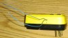
Well, it's an old thread, but it's an interesting topic and something I've wanted to build for my 10 A Variac when I mount it in a better box (it's in a "temporary" particle board box I made 40 years ago ). My approach to this is to use an off-the-shelf GFI and run a wire through the GFI's current transformer. I picked one my wife found at a second-hand store for a buck with the name "Shock Buster". The attached pictures show how easy it was to modify (I first tried this with an old GFI I put in our bathroom 20 years ago that was replaced and I broke the small wires; but it would also work in principle). The GFI will trip when you run enough 60 Hz current through the blue 24 gauge wire. I wound a current transformer from a ferrite toroid I had, but I don't like its magnetic characteristics, so this project is stalled until I get a decently linear method of measuring the AC current. Next step is probably to purchase a commercial 20 A current transformer. This will then be averaged or run through an RMS detector and given to a comparator which gates an AC signal to trigger the GFI.
Hopefully, maybe one of you experienced EEs will design some circuits for us hobbyists. I've tested the tripping of this GFI breaker using this added wire and it works well, but of course messing with line stuff like this is probably best avoided by newbies -- and you'd not want to rely on this GFI for actual GFI behavior (my Variac box will include an upstream unmodified GFI).
My original idea was simply to monitor the AC current and connect a resistor across hot to ground. But this has the undesirable effect of also tripping any upstream GFI. Murphy's Law would dictate that it's one you're unaware of or behind that bookcase full of books (in fact, that's exactly the situation I would have faced before I moved my bench into the next room...).
Using a GFI unlatching relay, if you want AC and DC tripping, use a Hall effect sensor for current (ACS756). These have relatively high output bandwidth so you can op amp rectify the output so sense output is always DC proportional to current. You can put an adjustable R-C filter to average the output to adjust the trip timing sensitivity and another adjustable control to set the absolute amperage level.
There are AC/DC mechanical breakers that use magnetic field trigger but they are fixed, both for absolute amperage and trip timing.
This site uses cookies to help personalise content, tailor your experience and to keep you logged in if you register.
By continuing to use this site, you are consenting to our use of cookies.

")