Continue to Site

Welcome to our site!

Electro Tech is an online community (with over 170,000 members) who enjoy talking about and building electronic circuits, projects and gadgets. To participate you need to register. Registration is free. Click here to register now.

  • Welcome to our site! Electro Tech is an online community (with over 170,000 members) who enjoy talking about and building electronic circuits, projects and gadgets. To participate you need to register. Registration is free. Click here to register now.

Using electret mic as input for tip31 for sound reactive leds?

Status
Not open for further replies.

unclesam93

New Member
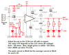
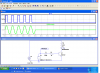
Making the leds reactive to sound with a audio input works fine, but I haven't been able to get an electret mic to work when I replace that as the input instead of the audio jack. I followed mic+lm386 amp circuits but it still isn't working.
 
You need to post your schematic or a link to your circuit so we can see how it should work.
Having said that; it sounds like you don't have enough gain for the small signal from the mic or you haven't supplied the voltage needed by the mic to work properly.
 
**broken link removed**

I realized where I might have also messed up. I was planning on using the output from that and connect it to the tip31 which would make the LEDs blink, but the trans would only be needed if I was using an audio jack right?
 
The picture didn't make it. (at least not for me)
Save it as a .png file on your computer, then go to go advanced and attach it.
 
Sorry, does this work?
 

Attachments

  • lm386_mic_amp1.png
    lm386_mic_amp1.png
    4.7 KB · Views: 1,147
Do you have the 10uf from pin one to 8? If it worked okay with the audio input it may just not have enough gain. The elerect mics only put out a few 10's of millivolts, so even with the gain of 200 it might just barely light your led. adding your transistor to the output would work better since it only needs .7 volts to turn on. Don't forget to limit the led current.
 
Yes I do have the cap from 1 to 8. Does the output go to the base of the transistor? What happens to the collector and emitter? I think last time I tried it with the tran the LEDs were completely lit up and not blinking.
 
The Instructable that used only a TIP31 power transistor as an LED driver circuit has many problems because it was designed by as 10 years old kid who knows nothing about electronics. It blows up the amplifier, LEDs and TIP31 transistor because it is missing resistors to limit current.

The LM386 can drive an 8 ohm speaker with peak current of 400mA so it is perfect as an LED driver circuit.
Its output pin is normally at half the supply voltage which will light red and yellow LEDs all the time. If a resistor powers a diode at 0.7V then a pot can apply the variable voltage to the inverting input pin of the LM386 to reduce the idle voltage until the LEDs do not light. Then sounds will light the LEDs.
The LM386 acts like a half-wave rectifier so the LEDs are lighted for half the time and their peak current is 40mA but their average current is 20mA.
Try it (I didn't).
 

Attachments

  • LEDs blink to sounds.PNG
    LEDs blink to sounds.PNG
    20.3 KB · Views: 1,706
Something like this might work.
 

Attachments

  • flash.PNG
    flash.PNG
    71.3 KB · Views: 708
Something like this might work.
You should not capacitor-couple into a transistor like that.
The base-emitter is a diode that slowly charges the capacitor but there is nothing to discharge the capacitor. So with a continuous signal the capacitor charges high enough that the transistor will not turn on.

Add a diode from base to emitter (cathode to base) to discharge the capacitor each cycle.
 
**broken link removed**
 
My bad. AG is right it needs the diode to keep the charge in ballance.

Haven't I seen the schematic above before somewhere?:confused:
 
So I finally tried it, and it works somewhat. I can get the led's to blink only if I blow into the mic. It won't react to music from a speaker. I tried adjusting the pot. Mic isn't getting strong enough signal?
 
So I finally tried it, and it works somewhat. I can get the led's to blink only if I blow into the mic. It won't react to music from a speaker. I tried adjusting the pot. Mic isn't getting strong enough signal?
Which circuit did you try?
What is the supply voltage of the circuit?

The LM386 circuit I showed should work perfectly with any voices or music in the room it is in.
 
I used the one you gave me, the supply voltage is 9 volts. I just remembered that I don't have the exact diode as the two that you mentioned. How much would that effect it? Also, where it says cap 1~10, I'm using a 3.3 uf cap.
 
AG is the expert, but I don't think a gain of 200 is enough to drive the LED's. If I recall the mic output is only 10 or 20 mv.
 
The 15mV RMS from a mic is when somebody is talking to it (70dB) about 10cm to 15cm away. If they talk a little louder (+6dB to 76dB) then the output level is doubled to 30mV. The peak voltage is 42mV.
The LM386 has a voltage gain of 200 so its output is a peak of +8.4V (it can't go that high) which is plenty to light the LEDs.
Usually the volume control is turned down to avoid clipping when an electret mic is driving an LM386 that is driving a speaker.

Maybe the mic or an electrolytic capacitor is connected backwards.
 
I am glad that you got it to work.
Send me a bottle of beer by courier.
 
Total Newbie

So I've searched the web for hours trying to figure out how to make some LEDs respond to music, and it seems I've finally found the solution, with the LM386 Audio guru has outlined here, so thank you!

I'm a software guy who has never really done any electronics or hardware hacking, but I'd like to try this as a first project, but I'm having a hard time converting the circuit diagram in to a parts list, I'd really appreciate it if somebody could help me with that.

Thanks!
 
Status
Not open for further replies.

Latest threads

New Articles From Microcontroller Tips

Back
Top