Electro Tech is an online community (with over 170,000 members) who enjoy talking about and building electronic circuits, projects and gadgets. To participate you need to register. Registration is free. Click here to register now.
Welcome to our site! Electro Tech is an online community (with over 170,000 members) who enjoy talking about and building electronic circuits, projects and gadgets. To participate you need to register. Registration is free. Click here to register now.
Not sure what you mean by filtering DC from an AC signal. You need to rectify the AC first to get pulsating DC then filter it with the capacitor. It doesn't need to be bipolar.
Not sure what you mean by filtering DC from an AC signal. You need to rectify the AC first to get pulsating DC then filter it with the capacitor. It doesn't need to be bipolar.
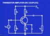
Alright then, let me rephrase the question. In this circuit, the lecturer describes the output of the microphone as AC. These capacitors appear to be unipolar. Is that going to work, or do they need to be bipolar?
No.
The input impedance of a typical 2N3904 transistor is shown on a graph on its datasheet. Then you don't need to calculate it.
If the collector current is 10mA then the input impedance is only 500 ohms because the emitter resistor has a bypass capacitor. The base bias resistors have fairly high values so they reduce the input impedance of the transistor to maybe 480 ohms.
If you want a cutoff frequency of 50Hz then the coupling capacitor value is 6.7uF which is a polarized electrolytic type unless you can find a non-polar one.
This site uses cookies to help personalise content, tailor your experience and to keep you logged in if you register.
By continuing to use this site, you are consenting to our use of cookies.