Continue to Site

Welcome to our site!

Electro Tech is an online community (with over 170,000 members) who enjoy talking about and building electronic circuits, projects and gadgets. To participate you need to register. Registration is free. Click here to register now.

  • Welcome to our site! Electro Tech is an online community (with over 170,000 members) who enjoy talking about and building electronic circuits, projects and gadgets. To participate you need to register. Registration is free. Click here to register now.

Using a transistor as a switch instead of an amplifier

Status
Not open for further replies.

svk

New Member
I'm trying to have a circuit, which is a simply LED flasher, to be either turned on or off depending on how bright it is. I'm using a photoresistor and a transistor to get this to work.

Here's what I have so far:
**broken link removed**

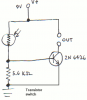
I unfortunately lost the specs sheet for the photoresistor, and I have little indication now of its resistance value. I have a multimeter, but it's analog and it's highly inaccurate. For example, it reports my 9V battery to be 13V. It's even more inaccurate for measuring resistance. But it looks like the resistance of the photoresistor ranges from 1K ohm in full light to about 40K ohm when I put my finger over it.

Regarding the 5.6K ohm resistor: I picked its value in order to drop the voltage down to about the required voltage to turn the transistor on.

The problem is that my transistor is currently operating as an amplifier. If there's a lot of light, my output has a lot of current; if there's relatively little light, my output has relatively little current. I want it to operate more like an on/off switch. What can I change to do this?
 
You've built yourself an emitter follower- the emitter of the transistor is going to look like the voltage at the base, minus an offset (Vbe, somewhere around .7V), unity voltage gain, large current gain.

What you need is a transistor amplifier with some gain - look in your text books/online for a "common emitter" amplifier. With enough voltage gain, and some nonlinearity (i.e. transistor won't turn on until vin >= .7V), you'll have something that looks like a switch.
 
The emitter of a transistor doesn't have any voltage gain. The emitter's voltage follows the base voltage.
The collector of a transistor has plenty of voltage gain when the emitter is grounded.
Wire it like this and adjust the value of the 5.6k resistor to change its sensitivity to light.
 

Attachments

  • Transistor switch.PNG
    Transistor switch.PNG
    13.9 KB · Views: 209
Thanks for the help, I have a working switch now. There's still a "gray area" where the circuit is half-powered, but it's significantly smaller now.

So let me get this right:
The voltage that comes out of the emitter is actually independent of what goes into the collector? Instead, it's dependent on the voltage at the base? Or am I oversimplifying... .

And this behavior of voltage is opposed to the behavior of current? I think I understand the current behavior. The current that comes out of the emitter is the current that goes into the base multiplied by the HFE value, correct?

I definately have to review transistors...
 
svk said:
Thanks for the help, I have a working switch now. There's still a "gray area" where the circuit is half-powered, but it's significantly smaller now.
Increase the gain by using a pair of transistors in a darlington configuration.

svk said:
So let me get this right:
The voltage that comes out of the emitter is actually independent of what goes into the collector? Instead, it's dependent on the voltage at the base? Or am I oversimplifying... .

And this behavior of voltage is opposed to the behavior of current? I think I understand the current behavior. The current that comes out of the emitter is the current that goes into the base multiplied by the HFE value, correct?

I definately have to review transistors...
Well, to get a feel for the emitter follower, ignore the fact that it is a transistor and think of the B-E junction as a diode - now what does the circuit then look like? Then work out the equations using the other transistor equation: I =ke^(vbe/vt) and calculate the output impedance of it...
 
use audioguru's circuit.

svk, you should figure out a way to get "The Art of Electronics" by Horowitz and Hill. It's pretty expensive but has all the info you are asking for and a lot more. For example, its got a really nice explanation of emitter followers in it. It's very expensive but I bet you could get your dad to spring for it.
 
svk said:
The voltage that comes out of the emitter is actually independent of what goes into the collector?
The collector is not an input.

Instead, it's dependent on the voltage at the base?
Correct. The voltage gain of an emitter-follower is 1.


The current that comes out of the emitter is the current that goes into the base multiplied by the HFE value, correct?
Yes. The current that comes out of the collector is also the current that goes into the base multiplied by the HFE value, and with a collector load resistor there is a voltage gain.
 
audioguru said:
The collector is not an input.
I have trouble not thinking of it as an input...

philba said:
you should figure out a way to get "The Art of Electronics" by Horowitz and Hill. It's pretty expensive but has all the info you are asking for and a lot more. For example, its got a really nice explanation of emitter followers in it. It's very expensive but I bet you could get your dad to spring for it.

Well, as it happens, I found a used copy for $20, after a considerable amount of searching.

I suspect it will be a pretty thick and dense book? Not something you could read without a pencil, calculator, and a stack of paper? Then I'll be mentally preparing myself...
 
svk said:
I have trouble not thinking of it as an input...


Well, as it happens, I found a used copy for $20, after a considerable amount of searching.

I suspect it will be a pretty thick and dense book? Not something you could read without a pencil, calculator, and a stack of paper? Then I'll be mentally preparing myself...

it doesn't hurt but it's a pretty clear read. there is just A LOT of it.

by the way, an indespensible companion tool for just about any electronics book is a spice simulator. while simulators aren't perfect, it is wonderful for putting together a circuit and trying out. you can make all sorts of changes quickly and see what's going on. I use switcher cad from linear tech. it's free. while they push it as a power supply design tool, it's pretty general. https://www.linear.com/company/software.jsp You could put your circuit into it and see if it works.
 
Status
Not open for further replies.

Latest threads

New Articles From Microcontroller Tips

Back
Top