Continue to Site

Welcome to our site!

Electro Tech is an online community (with over 170,000 members) who enjoy talking about and building electronic circuits, projects and gadgets. To participate you need to register. Registration is free. Click here to register now.

  • Welcome to our site! Electro Tech is an online community (with over 170,000 members) who enjoy talking about and building electronic circuits, projects and gadgets. To participate you need to register. Registration is free. Click here to register now.

Using a PIC to measure AC frequency

Status
Not open for further replies.

Futterama

Member
Hello forum,

I have a simple gasoline engine (like Zenoah 26ccm for RC cars) with a ignition coil that has a special output - when the output is shorted, the engine stops (shorts the ignition somehow).

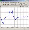
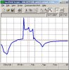
The output is some kind of AC, I'm not sure it's a perfect sine, but sorta. The voltage varies with speed, but it's about 40VAC at idle and rises to more than 100VAC when I open the throttle.

I would like to measure the frequency of this AC with a PIC, since it equals the engine rotational speed.

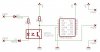
I don't want to load this output much, because I don't know if this would affect the ignition, so I would like some high-impedance circuit.

I saw Nigel mentioning zero-crossing circuits in another thread, is this the way to go?

I'm not much familiar with AC circuits, so consider me as a rookie :)

Any suggestions are very welcome.


Regards,
Futterama
 
Yup zero crossing circuits is the way to go. It doesn't need to be a sinusoid, but you do need it to be periodic and you need to know how many times it crosses zero per cycle (though you don't need to know exactly where since it's probably spinning fast enough that you can probably wait until it's done a full rotation before getting the next speed update.
 
YOu responded before I found a previous thread I had:
https://www.electro-tech-online.com/threads/review-zero-cross-detector-please.26259/?highlight=cross

DIagram of interest from that thread courtesy of NIgel:
https://www.electro-tech-online.com/attachments/zero_cross-gif.10706/

You might not need a transformer if the AC voltage is low enough which it probably is. (you could probably just clamp it with diodes or something to keep the voltage within the limits of the diode rectifier and transistor. The regulator block is to power other circuits too if your engine is able to power other things and you want it to do so. Otherwise just remove it (VR1) along with the capacitors, and D1. If you used a NMOS transistor then you could just replace all the resistors with shorts (the top of the MOSFET needs to feed into whatever power supply the rest of your electonics is using still, in this case +5V from somewhere else.
 
Last edited:
Using the voltage to drive the base of a transistor, wouldn't this load the output?

I see the point in using the bridge rectifier and the transistor, but what is D1 for? Protecting against reverse current into the bridge from the input cap when disconnected from mains?

Also the high voltage from the ignition coil (40-100VAC) - wouldn't it fry the transistor?

I was thinking something like a high input impedance comparator with a clamping diode to substitute the transistor...

Edit: I just saw you edit now, and a MOSFET could also be used, thats right, with a clamping diode on the base. I've got high-voltage bridge-rectifiers, so I would probably place the clamp between the bridge and the MOSFET.

The other day I asked a question about driving a MOSFET gate from a PIC, and I ended up using a 100ohms series resistor - would this be nessasary in this case too?

More edit: Actually the MOSFET is not a good idea, since it has gate capacitance, a comparator would probably be better, or am I wrong?
 
Last edited:
Futterama said:
Using the voltage to drive the base of a transistor, wouldn't this load the output?
THe only thing that won't load it is no output. I presume the engine won't have any trouble with such a small load. It's a very good approximation of no-load in this case.

Futterama said:
I see the point in using the bridge rectifier and the transistor, but what is D1 for? Protecting against reverse current into the bridge from the input cap when disconnected from mains?
It may be there to provide a voltage drop for the regulator since the voltage might be a tad too high still. It may also be there for safety. I don't think it's necessary in all cases.

Futterama said:
Also the high voltage from the ignition coil (40-100VAC) - wouldn't it fry the transistor?
THat's what the transformer is for. THis circuit was originally meant to be used to detect zero cross on a 115/230VAC mains in the first place.

Futterama said:
I was thinking something like a high input impedance comparator with a clamping diode to substitute the transistor...

Edit: I just saw you edit now, and a MOSFET could also be used, thats right, with a clamping diode on the base. I've got high-voltage bridge-rectifiers, so I would probably place the clamp between the bridge and the MOSFET.

The other day I asked a question about driving a MOSFET gate from a PIC, and I ended up using a 100ohms series resistor - would this be nessasary in this case too?

More edit: Actually the MOSFET is not a good idea, since it has gate capacitance, a comparator would probably be better, or am I wrong?
It is capacitive true, but it's very small relative to your engine. Plus...think about what a comparator is made up of...a bunch of transistors. The resistor is to slow down how fast the MOSFET turns on (yes! it's gate capacitance is small enough that it often turns on too fast! that's how small the load is!) Since it's a signal transistor and not a power one, you can reduce the capacitance even more by choosing a tiny one that handles barely any current. You only need it to pass enough current between source-drain for to pull the output low.

CORRECTION: I realize I made a mistake earlier saying that you can remove all resistors if you use a MOSFET. You still need the resistor above the transistor since that pulls PULSE HI, and when the zero cross is detected the transistor turns on and pulls PULSE LO. You must have the base transistor if you use a NPN BJT. The gate resistor (the MOSFET's gate is the equivelant of the base on a BJT, different names), then it is optional. It's used to slow down how fast the transistor turns on. It's not required in this case since the currents being passed are so low.

EDIT: There is one situtation where you might want a comparator rather than a MOSFET. You say the voltage might vary from 40VAC-100VAC. If this is the case, you might not be able to use a transformer to step down 100VAC enough to protect all the other electronics while still being able to reach the NMOS's gate threshold voltage to turn it on when it happens to be at a minimum of 40VAC. The gate voltage can be 1.8V, 3.3V, 5V, or 10V, depending on the transistor but is often 5-10V. Then you'd want a comparator so you could step down the voltage a lot to step down 100VAC low enough but still be able to detect the even smaller signal when it was 40VAC.
 
Last edited:
I'm not sure about the load issue, you have to remember, it is an ignition coil, made to produce a high voltage for the sparkplug, and then it has low current capability. And the output is only designed for stopping the engine, not for driving electronics.

Regarding the transformer - the circuit shown was for a mains supply, not an ignition coil. I'm sure if I connect a transformer, the copperwindings will function just like a wire, and the output will be shorted, and the engine will stop.

Regarding the MOSFET, again, it requires current to charge the gate, and current is what I don't have ;-) The comparator needs very little current to sense, even though it's built with transistors ;-) The Input Leakage Current for the comparator I'm looking at, is only 0.01nA typical and max 5nA!
 
The transformer will decrease the voltage and increase current in the process. I wouldn't worry about it too much. The 5nA may be current required to fight the leakage current of the gate capacitance gate capacitance. Because a NMOS is the same thing- it's steady state on-current is also very low- but what matters is that initial current pulse required to charge the the capacitorthe that counts.

For educational purposes, take a look at this transistor:
https://www.electro-tech-online.com/custompdfs/2007/11/2N2F2N7000.pdf
Around 10nA leakage current.

So you can use a NMOS and pull-up resistor, or replace both with just a comparator. THe biggest difference that you'll actually notice is the logic will be inverted between the two setups. Use what you want. Also, you can reduce the current required by using that gate resistor, at the expense of a transistor that turns on a bit slower- but who cares...it can switch on and off many orders of magnitudes faster than your engine can rotate.

Do you know the speed that your engines rotates at? If it's AC, then it shouldn't short the transformer (only happens with DC). Keep in mind most transformers are designed to be used at 60Hz. THat's about as close to DC as you get without actually being DC for most things. Does your engine spin at 60 RPS (3600RPM?) or significantly slower?

FYI: A transformer coil might just be wire, but it has much higher inductance due to it being wound up so it won't short out AC- only DC. The inductance will slow down the rate that current can change in it so if it's AC, the voltage will reverse driving current in the opposite direction before it ever gets to "short-circuit levels".
 
Last edited:
My point is, there is probably not enough current to generate a magnetic field inside the transformer in the first place. And it's not the transformer that shorts, it's the ignition coil.

Well, I don't have a suitable transformer anyway.

The problem about the MOSFET is that when it's not charged, and the voltage rises but with low current capability, the MOSFET will charge slowly, and it will "hold down" the ignition coil output voltage at the same time, and perhaps the ignition coil will "see" this as a short. I'll have to do some testing on the output to check the actual current capability and to see how big a load I can put on it, before the engine starts to cough.

The engine runs at max 20,000-25,000rpm and I think idle is around 2000-3000rpm, but I'm not sure about the idle, it's a guess, the max rpm of 20,000-25,000rpm is a fact ;-)
 
The MOSFET capacitor is very very small small. I still think that your concerns aren't as big as you think they are though. It's mainly becuase you are making it sound that your engine's current is on the same order of magnitude as a single MOSFET transistor's gate current. But if it doesn't generate enough current to turn on the smallest transistor and it really is that sensitive, then nothing is good enough. I do see your concern about energizing the transformer though since that does take a bit more current. If that is the case you are going to have to use clamping diodes (and resistors to drop off the extra voltage across)instead of a transformer.

The reason your engine shuts off when you short it is because it makes the voltage between the two terminals the same so that a voltage difference cannot form to make the spark.

Well, until you have an idea of how much current the ignition coil can drive it's all moot. It doesn't seem I can convince you not to worry, and if you worry that much you're going to run some tests anyways. Maybe you could try testing it by connecting a 100kohm resistor across the shut off terminals and see if it still runs. Or you could just connect a multimeter across the terminals to measure the voltage. If it's as sensitive as you think then the multimeter would not be able to read the voltage properly (or the engine would be unable to run). Safety first of course, but if the current is as low as you think then it's less dangerous than get shocked by static.
 
Last edited:
I have now tested the output, and I was wrong. The output can easily drive a 100ohm resistor without stopping the engine.

I also took my scope and made a few pictures of the "typical" sine-like output voltage (see below).

Now my problem is that it does not look that much like a sine, and the scope picture also changes randomly (higher peak voltage and changed "look" of the voltage curve).

So I'm trying to figure out how to read this but I'm kinda stuck.

Assuming the engine could run with a max of 30,000 rpm, there would be a voltage curve every 2ms and the "width" of this output will be a lot smaller than on the pictures. The voltage will also rise when rpm goes up.
The "abnormalities" of the output is also a problem.

I would like to use an optocoupler to seperate the coil-voltage from the rest of the system (PIC ect.). I've got a few of these from Fairchild I would like to use:

https://www.fairchildsemi.com/pf/FO/FOD817D.html

See the schematic - this is how I was thinking of connecting it. The pads to the left is where the output voltage from the ignition coil will be applied. The output to the PIC is to the right.

Any ideas how I can read the output voltage spikes with the PIC?
 

Attachments

  • output1.jpg
    output1.jpg
    38.6 KB · Views: 332
  • output2.jpg
    output2.jpg
    38.1 KB · Views: 274
  • opto_circuit.jpg
    opto_circuit.jpg
    29 KB · Views: 594
Last edited:
When looking at the output voltage curve, perhaps it would be better to just read all the voltage spikes into the PIC, and then make the PIC decide whether the signal was a double or triple spike or it was 2 or 3 rounds.
The 0V pause/gap between the spikes is quite big, so this could help the PIC determine the rpms.
 
Nigel, do you mean one square per round or a square for each "spike" above 12V?
The PIC should be able to read the output from the opto, but perhaps I need something with hysteresis since the PIC digital input pin have an undefined voltage area. Is it here you think a schmitt trigger will do the job?

By "schmitt trigger" you mean a comparator with hysteresis, right?
 
Last edited:
Futterama said:
Nigel, do you mean one square per round or a square for each "spike" above 12V?
The PIC should be able to read the output from the opto, but perhaps I need something with hysteresis since the PIC digital input pin have an undefined voltage area. Is it here you think a schmitt trigger will do the job?

It's what schmitt triggers are made for!.

By making a schmitt round a comparator, you can adjust the actually slicing point as well!.
 
Nigel, I found a 74HC14 that I'll use.

If you look at my schematic, do I need 2 high voltage diodes (RS1M), one at each side of the opto emitter, or is 1 enough? The emitter can't handle the high reserve voltage from the coil and I'd rather use 1 or 2 rectifiers instead of 1 bridge rectifier - to simplify the output from the opto to the PIC.
 
Status
Not open for further replies.

Latest threads

New Articles From Microcontroller Tips

Back
Top