Continue to Site

Welcome to our site!

Electro Tech is an online community (with over 170,000 members) who enjoy talking about and building electronic circuits, projects and gadgets. To participate you need to register. Registration is free. Click here to register now.

  • Welcome to our site! Electro Tech is an online community (with over 170,000 members) who enjoy talking about and building electronic circuits, projects and gadgets. To participate you need to register. Registration is free. Click here to register now.

Using a MOSFET as a diode replacement?

Status
Not open for further replies.

blueroomelectronics

Well-Known Member
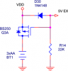
I recall seeing a P-Channel MOSFET used in place of a diode to reduce power loss over a diode in a power supply circuit. The picture below is provided for clarity (I'm only interested in the Q1 part)
Can I use a N channel MOSFET like a 2N7000 if I connect the gate to VBattery?

**broken link removed**
 
You can as long as the rating aren't exceeded. It is not clear to me though, how this would reduce power loss. Generally, in order to reduce power loss in switching applications, the diodes should be fast (schottky) and or have low forward drop (again schottky). I rather doubt the 2N7002 body diode performs as well.
 
I've been wondering that as well. I think I've come to the conclusion that it's just easier to find large transistors (with an equally large intrinsic diode) rather than to find an equivelant, equally large dedicated diode. The intrinsic diode just switches slow though but if that doesn't matter...then it doesn't matter! I'm not sure why the gate is connected to ground. It would seem that if you shorted gate-drain, the same thing could be accomplished either a NMOS or PMOS on the high-side.

EDIT: NOw that I think about it more, it seems that the intrinsic diode isn't really being used in your circuit (see reasoning in above paragraph). It would appear that when the battery is connected properly, the MOSFET actually turns on allowing current to pass "in reverse through the transistor" (albight the intrinsic diode also allows this, but since the MOSFET is on and much better conductor than the diode, the current bypasses the instrinsic diode). If the battery polarity is reversed, then due to the way ground is connected the MOSFET just shuts off since the gate is now essentially tied to +V. So if this reasoning is correct, then you could only accomplish the same thing with an NMOS on the low-side (with gate connected to +V) which has the obvious disadvantage of disrupting ground.

What I find really neat is that it seems to use the intrinsic diode to get the whole process started: once current is flowing the source terminal approaches the drain's voltage which pulls the source voltage away from the gate voltage enough so that the transistor turns on. Once that happens the source-drain conduction becomes self-sustaining and the diode shuts off. I don't think it would work without the intrinsic diode there.

Although, if you needed a giant slow-swithcing diode you could just short the gate-source of any transistor and use it. But I think my EDIT makes more sense on the part of an "active transistor".
 
Last edited:
Well I've seen it before as a almost zero on diode (I think it was nat-semi in an app note) There is a little more info on Robot-Rooms website. https://www.robotroom.com/RoundaboutPCB.html
**broken link removed**


Right side of picture: Protection with lowest voltage drop. Install a logic-level p-channel power MOSFET such that the gate, drain, and source pins are respectively in the 'G' 'D' and 'S'. Roundabout's PCB is designed with the IRFU5505 in mind, such that the metal tab would face the 'G D S' label. See pages 103-107 in Intermediate Robot Building for more information on the advantage of using a power MOSFET instead of a Schottky diode.
 
blueroomelectronics said:
Can I use a N channel MOSFET like a 2N7000 if I connect the gate to VBattery?

Q1 has to be a P type if the transistor is used on the + end of the battery. Note that the MOSFET is connected "backwards" on purpose because the FET will conduct in both directions. Rather than using a rectifier diode which has ~0.7V or higher voltage drop, the voltage loss across the FET will be much smaller. Calculate V(drop)=IR where I is the current draw of the circuit and R is the Rds(on) resistance of the FET.

If you used a N type, the source and drain connections would have to be reversed with the source connected to B+, and the gate biased about 10V higher than your available battery voltage.

A smarter way to design this would be to use a N channel MOFET version of the "diode" circuit between battery - and ground. If effect, a mirror image of the diagram shown. N channel FETs tend to have much lower Rds(on) and cost much less. I would not use the 2N7000 family. I think it's too low power.
 
Last edited:
With an N channel device, doesn't Vgs need to be ABOVE V+ for the mosfet to conduct? If it is conducting, Vs is very close to Vd and thus Vgs would need to be at least Vgs(th) + V+. Hence, they use a PMOSFET there. I think it's the same issue with using NMOS devices on the high side of an H Bridge. I assume the max1614 puts out the higher voltage to allow the N channel devices to work.

The way I think about the voltage drop is if you can get the MOSFET to fully turn on, you will have an Rds per the datasheet. Then use that to determine voltage drop (I*Rds). So, for high current applications, a diode may well be better. For lower current, say up to 2A but depending on the Rds, the MOSFET is better. For example, with an Rds of 100 mOhms, a 1A draw will see a 100 mV drop but 10A will see a 1V drop.\

edit: damn bob, ya beat me to it!!!
 
If you want to use an n-channel device, simply stick on the negitive side of the supply, since it's only for protection it doesn't matter.

Aslo beware of supply voltages higher than the MOSFET's maximum gate voltage so if you want to use this circuit on a 24V system then use a potential divider or even a zenner to limit the gatevoltage to a safe level.
 
Actually it's for running it on battery when main power fails.
 

Attachments

  • P-FET_Battery.png
    P-FET_Battery.png
    11.4 KB · Views: 3,709
That should do the job providing you BS250 can pass enough current when its gate voltage is -3V (when the battery has worn down a bit).

You could use an n-channel MOSFET if you reversed the polarity of the battery, supply and diode.
 
Hmm, thanks Hero999 I've got a couple BS250 laying around I'll hook them up. The 16F917 has a programmable low voltage detector 4.5V thru 2V. Should be handy for detecting when the power has failed (switched over) and when the battery is too low.
 
Status
Not open for further replies.

New Articles From Microcontroller Tips

Back
Top