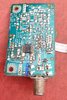
according to the pic of the top of the board, it's I2C.... if the receiver still works somewhat, you could connect an I2C "sniffer to the board, and record the data sent for tuning the module and work out what the instructions are... or find another Sony receiver in a similar model or around the same time frame of manufacture, and record the I2C data from that.... i've seen the insides of many Sony receivers, and unless it's a major change of technology, sony rarely re-invents the wheel.... their "low-to-mid" range of models have used the same main PC board for many years...
Perhaps it's different over there?, but as an ex-Sony service dealer I've seen the insides of a great many as well - and unless they are the same model, they are entirely different from each other. Historically Sony didn't keep models for more than a year, and each year would be a completely different.
The I2C data would depend entirely on the exact tuner module, and the PLL IC fitted, and they never seemed very standard across models - but any 'later' Sony audio gear tended to be made in China, if not actually designed in China as well.
using 50 ohm antenna designs to feed a 75 ohm input is really not a problem, you lose about 1 to 2 dB of sensitivity from the slight mismatch. if you are building yagis, you will gain more than that back.
If you're buying an unbalanced FM aerial, then it's going to be 75 ohms anyway, as far as I'm aware they don't make 50 ohm ones?. And if you're building one, then simply build a 75 ohm one. You don't want to lose a couple of dB, if you're using yagis (and why wouldn't you?) you're probably looking for long distance reception anyway (I used to use an 8 element yagi, on a rotator). If you're in a strong area, and only want local stations, a bit of wire is all you need.
I used to use a Grundig R-45 receiver, which was incredibly sensitive on FM, and out performed any Japanese receivers I ever tried. The R45 was a
VERY expensive unit, but we got them (and huge amounts of other Grundig gear) dead cheap, as we took the entire stock from the Irish division when it was closed, after the boss was murdered by the IRA terrorists.
") Some question arose:
Some question arose: