Continue to Site

Welcome to our site!

Electro Tech is an online community (with over 170,000 members) who enjoy talking about and building electronic circuits, projects and gadgets. To participate you need to register. Registration is free. Click here to register now.

  • Welcome to our site! Electro Tech is an online community (with over 170,000 members) who enjoy talking about and building electronic circuits, projects and gadgets. To participate you need to register. Registration is free. Click here to register now.

usb to rs232 serial cable

Status
Not open for further replies.

Parth86

Member
hello ,
I want to burn hex code from Laptop to p89v51rd2. but I don't have usb to rs232 serial cable

laptop -aspire746
os- window 7
serial port
microcontroller nxp89v51rd2
compiler - keil
programer software - flesh magic
com port 1
baud rate 9600
interface - none ISP
max RS232IC

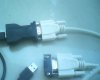
usb to rs232 serial cable is not available in my place so I used two cable to burn hex code I have driver cd
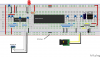
programmer circuit +Db9 male connector +db9female connector------cable-----db9 female+db9male--able --- usb port to laptop port

Q. it will work ? or tell me how to burn hex code
 

Attachments

  • IMG_0043.JPG
    IMG_0043.JPG
    66.6 KB · Views: 403
  • IMG_0042.JPG
    IMG_0042.JPG
    71.7 KB · Views: 426
Should work... You seem to have a USB to RS232 converter in your image!!

Just try it.... It will either work or not.... Just make sure Txd goes to Rxd throughout... Your setup is no different to said cable anyway..
 
thank you Ian sir


how to know that my controller and programmer circuit is working correctly

so I used multimeter I connected 9 v dc battery and I measured supply voltage for microcontroller I got 3.95 vdc and I saw 3.65 vdc for programmer circuit

so my controller and programmer circuit is correct ?
 
Last edited by a moderator:
you mean datasheet .at this time I don't have good quality picture. I have image that you gave me in another post
I have made this connection on bread board .

I used multimeter I connected 9 v dc battery and I measured supply voltage for microcontroller I got 3.95 vdc and I saw 3.65 vdc for programmer circuit

look at this code and tell me its correct
look at this assembly code
Code:
      org 00h

      Setb P3.2              ; Led on
      clr   P3.2           ; Led off
 
       delay:
    mov    R1, #20
    mov    R2, #0
delay1:    djnz    R2, delay1
    djnz    R1, delay1

   ret
   end

hex code
Code:
:0D000000D2B2C2B379147A00DAFED9FC2224
:00000001FF

I tried to burn hex code but I got message reset device in ISP mode now ?
 

Attachments

  • Vead.png
    Vead.png
    250 KB · Views: 728
Last edited by a moderator:
Vead. Slightly off topic, but why "No link here" in your breadboard graphic? Is that jumper position acting as an "On/Off"?

Just wondering...
 
Vead. Slightly off topic, but why "No link here" in your breadboard graphic? Is that jumper position acting as an "On/Off"?

Just wondering...
I think I can see why...

There is 9V to the right of the missing link and 5V to the left. Inserting a link would provide 9V to the ICs, which is much to high.

I see no connection from lower ground rail to upper ground rail - that might be the problem.

If the voltage regulator is 5V, and you only get 4V out, either your battery is flat, or there is a fault in the circuitry somewhere
 
Yes I drew that circiut for my tutorials.... The breadboard has no connection under the middle... I have used 9v on one side and 5v on the other..

vead Read through the tutorial as you need a toggle switch to reset the micro to bootloader mode
 
Vead. Slightly off topic, but why "No link here" in your breadboard graphic? Is that jumper position acting as an "On/Off"?

Just wondering...
actually this is not original circuit now I am using 9 vdc and controller get the 4.16 vdc

I am trying to burn code I am getting message reset device in ISP mode now I think I need reset switch But I don't have reset switch
 
Status
Not open for further replies.

New Articles From Microcontroller Tips

Back
Top