Continue to Site

Welcome to our site!

Electro Tech is an online community (with over 170,000 members) who enjoy talking about and building electronic circuits, projects and gadgets. To participate you need to register. Registration is free. Click here to register now.

  • Welcome to our site! Electro Tech is an online community (with over 170,000 members) who enjoy talking about and building electronic circuits, projects and gadgets. To participate you need to register. Registration is free. Click here to register now.

Urgent RC help! Very simple! (but not for me =)

Status
Not open for further replies.

brodin

New Member
Look at the images.
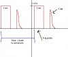
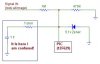
The PIC is going to meassure the time between the two "trig pulses" but i have a "crap" that is disturbing. I suppose i could get rid of it with a RC Filter, but I am so terribly bad at analog electronics.

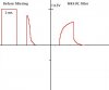
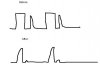
I suppose that the 2ms pulse will look like the pulse in signal2.jpg when using a RC filter.
But that's no problem. So i just want to get rid of the crap so there is just free space between the two trig pulses!

How do i figure out what values i need for this on the resistor and on the capacitor.
And what kind of capacitor should I use? A electrolyt or something else?

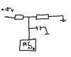
Please tell me if you see something else in the scematic that is not needed or used wrong.

I can also tell that this signal comes from a motorcycle tachometer, and this circuit will be used as a shiftlight.
The time between the two pulses differs so much so i can't just set a minimum time(in software) to ignore the "crap pulse", because at high RPM the time between the 2ms pulses will be very small!
 

Attachments

  • signal.jpg
    signal.jpg
    19 KB · Views: 474
  • circuit_309.jpg
    circuit_309.jpg
    12.1 KB · Views: 494
  • signal2.jpg
    signal2.jpg
    14.1 KB · Views: 478
brodin said:
The time between the two pulses differs so much so i can't just set a minimum time(in software) to ignore the "crap pulse", because at high RPM the time between the 2ms pulses will be very small!

I don't see any way you could use a simple filter to remove the second pulse, it would also remove the first pulse. Although you could try filtering it and using a comparator to detect signals above a certain level - but the wide variations in frequency are likely to mess up any filtering.

For a start though, why have you got this second pulse? - presumably you have a fault somewhere? - what type of sensor are you using?.

If you can't repair the sensor, you could do it in software, you don't need to set a minimum time, simply ignore every second pulse. As you're timing from rising edge to rising edge, it doesn't even matter if you use the good pulses or the bad pulses, the time should still be the same.

So simply detect a leading edge, start your counter, wait for the next leading edge, but leave your counter running, then wait for the next leading edge - where you stop your counter, giving the time you're looking for.
 
I don't see any way you could use a simple filter to remove the second pulse, it would also remove the first pulse.
I thought that if i made a filter that filter the first ms of the pulses, then the crap would dissapear because that pulse is just 0.5-1 ms. The 2ms pulse would then just become 1 ms, but that would not matter. Is my theory possible?

For a start though, why have you got this second pulse? - presumably you have a fault somewhere? - what type of sensor are you using?.
I am using the bike's(Honda CBR 600) internal sensor that is made for the original tachometer.


So simply detect a leading edge, start your counter, wait for the next leading edge, but leave your counter running, then wait for the next leading edge - where you stop your counter, giving the time you're looking for.
You are so right about this, this is probably the easyest way to do it!
 
So simply detect a leading edge, start your counter, wait for the next leading edge, but leave your counter running, then wait for the next leading edge - where you stop your counter, giving the time you're looking for.

There is a problem with this method though. Because when i rev it really much the crap signal comes to close to the trig pulse to it dissapears. So then i just have 1 pulse.

Would it be possible to do it with a RC as i said? How do i figure out the values then?
 
brodin said:
Would it be possible to do it with a RC as i said? How do i figure out the values then?

You can't filter out one pulse but still leave the other, you could perhaps heavily filter it to give a DC voltage, the voltage depending on the frequency of the pulses - which is perhaps what the original tacho did?.
 
I don't understand why this would not be possible?

I think the picture says what i mean. I don't mean that i want to filter away the crap and keep the trig pulse. I mean i will filter both, but the trig pulse will still work as a trigpulse because it is longer and will survive the filtering.

Isn't that possible?

I mean if i have the correct value of a cap and the resistor, i thought it would be possible to time it so that it will kill the first ms of all pulses, which would mean that the second would dissapear because it is just 0.5 ms long.


Edit: Forgot picture
 

Attachments

  • fil.jpg
    fil.jpg
    16.4 KB · Views: 436
I don't think it would be possible, also don't forget - a filter will only work at one specific frequency - your application is a long way from one frequency!.

BTW, what happened to the original tacho?.
 
BTW, what happened to the original tacho?

I am using this bike for roadracing, so it is not a registred bike. It has no original instrumentation. But there is a "racing tacho" on it which is connected to the primary side of the ignition coil. It is bought as an accessory tacho. So the signal i am using is only used for my circuit, not for another tacho.

Maybe i should try the method of connect a large cap and use a 12F675 with A/D instead. How do i connect that cap then? Do i need a resistor then? Can you please make a easy drawing.
 

Attachments

  • ad.jpg
    ad.jpg
    9.3 KB · Views: 422
There is a simple solution. Just take the pulse (with no filtering) to a PIC input. Start a timer when the rising edge of the incoming pulse arrives.

Continue to monitor that the pulse is present for 1.9mS. If it is, then the pulse is valid and you can record it. If not, reject it. Wait for the pulse to go low before repeating the cycle.

Yeah, that would probably work. I'll try that.
 
Status
Not open for further replies.

New Articles From Microcontroller Tips

Back
Top