Continue to Site

Welcome to our site!

Electro Tech is an online community (with over 170,000 members) who enjoy talking about and building electronic circuits, projects and gadgets. To participate you need to register. Registration is free. Click here to register now.

  • Welcome to our site! Electro Tech is an online community (with over 170,000 members) who enjoy talking about and building electronic circuits, projects and gadgets. To participate you need to register. Registration is free. Click here to register now.

Urgent help needed-Preamplifier

Status
Not open for further replies.

craz

New Member
Hello,
Could you guys please tell me how to build pre-amplifier with condenser
microphone as its input. I actually hav to build audio amplifier with all three pre amp , tone control filter and power amplifier, but output of pre amp is not coming.
Please help.

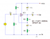
I have attached the schematic below which i tried to use but its not working.
 

Attachments

  • tl071_mic.png
    tl071_mic.png
    4.9 KB · Views: 195
Assuming you really mean a condensor mike?, then they require a 48V phantom power supply - even assuming you mean a cheap electret capsule, they need power as well.
 
i didn't understand actually wat u mean by connecting a phantom power supply,
as ths condensor mic has only two terminals for the input. :(
will that schematic work if i not connect any phantom power to condenser mic.
 
Nigel Goodwin said:
You're still not explaining what your mike is, but in either case I mentioned previously it probably needs power to work.


yea its tht cheap electret type condenser mic only, and i confirmed that it does not require any power, but other thn tht can you help me in schematic..as why tht circuit is not working?
 
craz said:
yea its tht cheap electret type condenser mic only, and i confirmed that it does not require any power, but other thn tht can you help me in schematic..as why tht circuit is not working?

How have you confirmed it needs no power?, because it does need power!.

For an example check one of the many 'bug' transmitters at **broken link removed**
 
The polarity of the input capacitor might be wrong when the electret microphone has a resistor added to power the FET transistor inside it, so use a non-polarized film capacitor. !0uF is way too high a value, use a 0.33uF film input capacitor for a response down to 20Hz.
 
i tried using Vcc and ground (sinousoidal wave) input instead of condenser mic inout but still the output is not getting amplified instead it get on dying down.
i tried with 15V sinousoidal input, output was around 2-3 Volt. And yea with frequency of 2KHz.
I also change the polarity of capacitor at the input end and also used low value but nothing seems to be working at this stage.
Pleaseeee help
 
craz said:
i tried using Vcc and ground (sinousoidal wave) input instead of condenser mic inout but still the output is not getting amplified instead it get on dying down.
i tried with 15V sinousoidal input, output was around 2-3 Volt. And yea with frequency of 2KHz.
I also change the polarity of capacitor at the input end and also used low value but nothing seems to be working at this stage.
Pleaseeee help

Well 15V is FAR too large an input, 15mV would be nearer the mark!.

How were you measuring the levels?.
 
An input of 15V is 42.4V p-p and would probably damage the opamp's inputs.
The opamp has a gain of 22k/1k= 22 so an input of only 91mV would give an output of 2V.

What power supply voltage did you use?
What load resistance did you use? It should not be less than 2k ohms.
 
audioguru said:
An input of 15V is 42.4V p-p and would probably damage the opamp's inputs.
The opamp has a gain of 22k/1k= 22 so an input of only 91mV would give an output of 2V.

What power supply voltage did you use?
What load resistance did you use? It should not be less than 2k ohms.

Well, im measuring the levels on CRO, power supply tht im using for opamp is 15V
and input 15V AC. I think i had given a large input supply 15V is bit too large, thats why i guess whenever i switch on the supply the signals were way too distorted and instead of any sinousoidal pattern there was a band. i will try with less input voltage, i hope this thing works.
thanks
 
yea thanks guys...that circuit finally worked...it is now giving a gain around 16,
when i used the input capacitor with reversed polarity.
so can you tell me tht is ths gain is enough to feed into the tone control filter, or i need to enhance it further.
Can i increas eby choosing any arbitarily value of resistor governing gain(22k)
???
thanks guys.
 
I was wrong before. The gain is R2/R1 + 1= 23.
You can use any value for R2 from zero for a gain of one, to 33M for a gain of 33 thousand and one. Use a 100k trimpot to adjust the amount of gain.
 
Status
Not open for further replies.

Latest threads

New Articles From Microcontroller Tips

Back
Top