Continue to Site

Welcome to our site!

Electro Tech is an online community (with over 170,000 members) who enjoy talking about and building electronic circuits, projects and gadgets. To participate you need to register. Registration is free. Click here to register now.

  • Welcome to our site! Electro Tech is an online community (with over 170,000 members) who enjoy talking about and building electronic circuits, projects and gadgets. To participate you need to register. Registration is free. Click here to register now.

URGENT. Can this project work?? Pls help me to modify.

Status
Not open for further replies.

themaestro

New Member
Hello there,
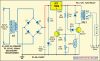
This purpose of this circuit is to switch on the bulb during nighttime and switch off the bulb during daytime. But so far i tested it on the bread board and it couldnt work. I dont know whether it's my personal problem or the schematic problem, can anyone help me on this?? plus, I would like to add a timer of 5hours to the circuit. The main purpose of the timer is to automatically switch off the circuit after 5hours ( assuming that the person sleeps 5hours after it's dark.) and repeats the cycle daily. A friend of mine suggested that i should put a timer in between the Zener Diode and the BC547 Transistor. But i'm unsure of the value. Just now when i was experimenting, the whole building short-circuited thrice. HELP PLS.... if possible pls attach a schematic as well.. thanks. my dateline is tomorrow =(

**broken link removed**[/IMG]
 
Last edited:
Hard to do without a schematic?
 
hi,
There is no circuit diagram on the PM you sent me.??
 
Sorry about that. Here it is.
 

Attachments

  • automatic-light-controller-using-7806-circuit-diagram.gif
    automatic-light-controller-using-7806-circuit-diagram.gif
    35 KB · Views: 536
Sorry about that. Here it is.

Disconnect your LDR from the circuit and measure with ohm meter the resistance of the LDR when it dark and light, let us know what you measure.?

EDIT:
Its works OK in simulation
 

Attachments

  • AAesp04.gif
    AAesp04.gif
    28.7 KB · Views: 189
Last edited:
Disconnect your LDR from the circuit and measure with ohm meter the resistance of the LDR when it dark and light, let us know what you measure.?

Just now i measured before. if i'm not mistaken, when bright, it's 100+k ohms. when it's dark it's 400k ohms
 
Just now i measured before. if i'm not mistaken, when bright, it's 100+k ohms. when it's dark it's 400k ohms

hi,
With that LDR the circuit will not work.
Change the values of the two resistors R1 and R2 to these values and it should work.
 

Attachments

  • AAesp05.gif
    AAesp05.gif
    30.1 KB · Views: 171
Last edited:
hi,
With that LDR the circuit will not work.
Change the values of the two resistors R1 and R2 to these values and it should work.

oh i see! Thank you very much for the info! By the way in the simulation, the value of the dc is 15V, where as the original one is 12v. Will it work the same by changing the R1 to 470k, and R2 to 50k?
Let's say that i was wrong about the values during bright and dark, how can i vary the values of R1,R2 when i measure the ldr values tomorrow? Should the value of R1 be higher than the resistance(dark) and R2 lower than resistance(light). Sorry for being so ignorant and shallow about the circuit.

hi,
The 12v is output of the transformer, which when rectified and smoothed will about +15V, so that will not affect the circuit.
Re-measure the LDR, light and dark, post what you measure.
 
hi,
The 12v is output of the transformer, which when rectified and smoothed will about +15V, so that will not affect the circuit.
Re-measure the LDR, light and dark, post what you measure.

I see. thanks for the explanation. I've measured the resistance. It's around 600k during dark. and it varies between 80~200k during light. I tested out the circuit just now but it still didnt work. When i switch on the ac from the right hand side(linked to the bulb and relay, you can see it from the schematic), and i turn on the left hand side ac, the bulb lights up no matter what happens to the brightness of the room. I dont know what went wrong. When i switch off the ac for the left hand side, i can hear the relay *click* once and switch.
 
The relay is activated when light ceases to fall on the LDR. The resistance of the LDR increases and the BC557 transistor turns off. This allows the voltage on the common terminal of the 7806 to rise and the output voltage rises.
When the voltage rises above 9v, the base of the BC547 sees a turn-on voltage and the relay is energised.
The original circuit is a very complex for such as simple task.
A much simpler circuit is shown below:
**broken link removed**

 
Last edited:
The relay is activated when light ceases to fall on the LDR. The resistance of the LDR increases and the BC557 transistor turns off. This allows the voltage on the common terminal of the 7806 to rise and the output voltage rises.
When the voltage rises above 9v, the base of the BC547 sees a turn-on voltage and the relay is energised.
The original circuit is a very complex for such as simple task.
A much simpler circuit is shown below:
**broken link removed**


Thanks for your reply. I have already done the PCB for the schematic that i've previously posted and i have to carry on with it because my dateline is 2 days from now, plus i have to write a 50 page report. Can you tell me what could have went wrong with my circuit? I checked all the parts n they were fine. But for the diode(D5) in my schematic when i solder it to the PCB, it is shorted. I used the multimeter to check the ends of the diode and there was a "beep" sound. The bulb would light up no matter what happened but now it couldnt light up at all. I think 1 of the parts might have been spoilt. Help me please. It's very important to me. By the way, i changed the white LED to a yellow one. the VR1=50k ohm. R2=470k ohm.
 
Status
Not open for further replies.

Latest threads

New Articles From Microcontroller Tips

Back
Top