Continue to Site

Welcome to our site!

Electro Tech is an online community (with over 170,000 members) who enjoy talking about and building electronic circuits, projects and gadgets. To participate you need to register. Registration is free. Click here to register now.

  • Welcome to our site! Electro Tech is an online community (with over 170,000 members) who enjoy talking about and building electronic circuits, projects and gadgets. To participate you need to register. Registration is free. Click here to register now.

(unwanted) 'magic' happening with 74LS164 shift register

Status
Not open for further replies.

schweini

New Member
Hi!

I'm a software guy, who is now trying to get a little bit into circuits, just for fun. I.e.: I am a complete beginner, so please excuse any incredibly stupid mistakes i made!

Now that that's cleared up:

I am trying to manually light up some LEDs with the 74LS164 8bit shift register.
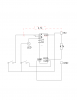
You can see a photo of my circuit (which I hacked together according to various pretty pictures I found online) here:
http://gometa.org/shift_register.jpeg

The idea is that the left push-button is supposed to set the input pins (1 & 2) to 5V, and the right push-button is supposed to set CLOCK pin to 5V, that the the...erm...registers may shift. The RESET pin is, right now, wired to Vcc via a 4.7kohm resistor (although i also tried it without the resistor)

The ULN2803 in the upper left corner is supposed to drive some bright LEDs someday, and isn't causing any discernible problems right now, so it may be ignored.

I am using the 5V (up to 2Amps) cables of an old external hard drive power supply to power this thing.

My problem is that nothing seems to work, and, even worse: very strange things are happening.

a) the buttons don't seem to do anything. The voltage on pins 1&2 or the CLOCK pin goes to 5V and all, but the output pins happily ignore that fact.
b) I noticed (on two separate ICs) that there is aprox. 1.2V between pins 1&2 and GND, even if I only connect Vcc and GND to the IC. I read somewhere that the IC only regards < 0.8V as 'off', so this might be a problem. Where this voltage is coming from, I don't know.
c) If I touch (!!!!) the CLOCK pin with my multimeter, all the outputs go up to 5V, and the connected LED merrily blinds me. If I touch the RESET pin, the outputs go down again. This intrigued me, so now i stumbled across the REALLY weird thing: if I touch those pins with an insulated wire, that is not connected to anything (!!) - not even my hand or GND - the same thing happens. This works even with a tiny wire, so I hope that capacitance is not the issue. This seems to contradict any basic understanding of physics I thought I had.

I googled around, and most of the internet seems to agree that
a) pull-up and pull-down resistors are nice and all, but shouldn't really be an absolute necessity for a simple thing like this (and, I don't quite 'grok' them)
b) I was afraid that I somehow fried my ICs, but noone else seems to have a problem connecting them directly to their power supply.

So, could anybody please give me a hint what the heck I am doing wrong? And why in the name of everything that is holy (and unholy) does the single end of an otherwise unconnected wire to the CLOCK and RESET pins make the IC do stuff (even if it's the wrong stuff), especially if blasting them with 5V doesn't seem to do anything at all?


Thanks, and sorry that this post got rather lengthy.

-M.

P.S.: Datasheet for the 74LS164: **broken link removed**
P.P.S.: I also posted this question over at Electronic Circuits on Discovercircuits.com - Free Electronic Circuits - I'm sorry about that, but I am desperate. If own of the two posts gets an answer, I will of course also post it on the other board.
 
You need pull downs on both your push buttons. Any input left floating will love your little bit of wire because it will pick up the 50/60Hz mains, like a little aerial, and rapidly switch that input.

If it still doesn't work, post a schematic.

Mike.
 
a) the buttons don't seem to do anything. The voltage on pins 1&2 or the CLOCK pin goes to 5V and all, but the output pins happily ignore that fact.


b) I noticed (on two separate ICs) that there is aprox. 1.2V between pins 1&2 and GND
Use 2K2 pullup resistors to +5V, on ALL switched input pins, else they will 'float' and you will measure only 1.2V

, even if I only connect Vcc and GND to the IC. I read somewhere that the IC only regards < 0.8V as 'off', so this might be a problem. Where this voltage is coming from, I don't know.
c) If I touch (!!!!) the CLOCK pin with my multimeter, all the outputs go up to 5V, and the connected LED merrily blinds me.
Again this is due to the fact that the clock pins is floating, use a pullup.

If I touch the RESET pin, the outputs go down again. This intrigued me, so now i stumbled across the REALLY weird thing: if I touch those pins with an insulated wire, that is not connected to anything (!!) - not even my hand or GND - the same thing happens. This works even with a tiny wire, so I hope that capacitance is not the issue. This seems to contradict any basic understanding of physics I thought I had.

I googled around, and most of the internet seems to agree that
a) pull-up and pull-down resistors are nice and all, but shouldn't really be an absolute necessity for a simple thing like this (and, I don't quite 'grok' them)
b) I was afraid that I somehow fried my ICs, but noone else seems to have a problem connecting them directly to their power supply.

hi,
I would always advise to use pull up resistors on any input when using LS IC's
You may also have electrically noisy switches, so a simple noise filter should be used on all your switches.
Also add some decoupling on the 5v line to 0V, sau 100nF and a 100uF capacitor.
Use a pull up also on the RESET pin.

OK.?
 
Thank you two for the quick reply.

Since I am still a bit confused about the whole pull-down and pull-up thing (I have read about it, but it still didn't really sink in), I tried the following:
a) I soldered together 3 AA Batteries. The mains electricity here in Costa Rica is horrendously 'dirty', so I wanted to eliminate that factor. Didn't help at all.
b) I connected pins 1 & 2 (the input pins) to +5V via a 7.5k resistor (which is the biggest i had lying around). Now, the voltage between pins 1 & 2 and GND rose(?) to 5V (instead of the 1.2V that were floating around before). Is that a good thing, or a bad thing?
c) Just for the hell of it i tried hooking those pins to GND instead of +5V via the same 7.5k resistor. That didn't nudge the 1.2V at all. Sigh.
d) re: noisy switches: the outputs go to 5V (that is called 'HIGH', correct?) even without looking at the switches. Just touching CLOCK does the trick right now.

Additionally, I wanted to add that:
a) If i simply hook up one of those ICs to +5V and GND directly via alligator clips, I still get those 1.x V
b) although I have read that pull-ups make the whole thing 'better', noone else seems to be needing them to get this thing to work in a basic fashion, as far as I can see. For 'professional' use: sure. But everybody else seems to just hook these things up, and go with it. Same with 'cleaning' capacitators. But I'd be happy to stand corrected.
c) how can the 'aerial' effect be more significant than the 5V that the right switch provides the CLOCK pin? That switch does NOT turn on the outputs - but touching that pin does.
d) re: posting a diagram: which free and simple program would you recommend for drawing this? I can't seem to find one which includes a shift register?

Thank you again for any help!

EDIT: Uh-oh. I was just reading up on pull-ups, etc., and now I am under the impression that the whole idea of sending 5V to the input pins in order to get them to 'signal to the IC to something' is wrong - am i completely reversed here? As in: should the pin be connected to GND or to 5V in order to get the IC to get an input?
 
Last edited:
hi,
Get this free download for drawing program.


If you don't add pull ups' [7.5k is OK], you are wasting your time trying to get the circuit to work.
You do not require pull downs.
If you just 'hook things up' as the 'so call experts' state you will get the problems that you are experiencing.

Your circuit may work OK sometimes and then not others, for a reliable, predictable circuit follow good engineering practice.
 
Last edited:
hi,
This should get you started with Expresspcb.

Download the *.sch file and open with Expresspcb.
 

Attachments

  • AAesp01.gif
    AAesp01.gif
    10.4 KB · Views: 755
  • 74LS164a.sch
    9.5 KB · Views: 183
You beat me to the drawing - i tried it in OpenOffice Draw, and came up with the attached rudimentary image.

Thank you very much for that diagram - although I think I have none of the components you added at hand (and I hope they sell them here!).

But: if I read that correctly, you are saying that a ....ermm....what a programmer understands as a '1' / 'true' is symbolized by basically shorting the input pin to GND (and I always thought that GND would correspond to '0' / 'false' ) ? If I did understand this correctly, this would explain my confusion regarding all this talk of logical levels - as I tried to draw in my diagram, I a pressed switch in my 'design' would connect +5V (instead of GND) to the pins!

But, on the datasheet I mentioned earlier, on page 4, I read something about the "High Level Input Voltage" having to be ABOVE 2V, and the "Low Level Input Voltage" BELOW 0.8V. So: am i reading this wrong? Or am I mistaken about the meaning of 'Low' and 'High'?

In my so-called diagram, I drew what I would have thought to be a pull-up resistor on the signal pins in red. This I have tried, but this (obviously) gave me 5V between the pin and GND (as a pull-up should?).

Also: I do understand that the pull-ups and -downs would be 'good engineering' - but may I have your blessing not to put in the capacitators, this being a purely experimental thing?
 

Attachments

  • circuit.png
    circuit.png
    24.6 KB · Views: 382
You beat me to the drawing - i tried it in OpenOffice Draw, and came up with the attached rudimentary image.

Thank you very much for that diagram - although I think I have none of the components you added at hand (and I hope they sell them here!).

But: if I read that correctly, you are saying that a ....ermm....what a programmer understands as a '1' / 'true' is symbolized by basically shorting the input pin to GND (and I always thought that GND would correspond to '0' / 'false' ) ? If I did understand this correctly, this would explain my confusion regarding all this talk of logical levels - as I tried to draw in my diagram, I a pressed switch in my 'design' would connect +5V (instead of GND) to the pins!

But, on the datasheet I mentioned earlier, on page 4, I read something about the "High Level Input Voltage" having to be ABOVE 2V, and the "Low Level Input Voltage" BELOW 0.8V. So: am i reading this wrong? Or am I mistaken about the meaning of 'Low' and 'High'?

In my so-called diagram, I drew what I would have thought to be a pull-up resistor on the signal pins in red. This I have tried, but this (obviously) gave me 5V between the pin and GND (as a pull-up should?).

Also: I do understand that the pull-ups and -downs would be 'good engineering' - but may I have your blessing not to put in the capacitators, this being a purely experimental thing?

hi,
In conventional discrete logic, high = +V = a logical '1',,,, low =0V = a logical '0'.

If you look at the 74LS164 datasheet you will see that either data 'A' or 'B' has to be high ie: +V for the clock on the opposite pin to generate a clock on the low to high going EDGE. This high going edge will shift into the LS164 either a high or low,,, '1' or '0' depending upon the state of the 'A'/'B' pins.

CLEAR is marked with a small circle which indicates it must be low 0V to be active.

Regarding the LED there should also be a low value resistor in series with the pin and the LED, say a 220Rish.

What is the purpose of this project.??
 
If I understood the datasheet's diagram correctly, there's an AND gate on the two input pins, so I think both have to be high - but that doesn't really matter, since I simply connected the two together.

So, If +V = high = 1 = true, am I thus inferring correctly that I do have to hook up +V to the switch and then to the pin? If this is the case, then I would need a pull-down resistor, to get that darn pin to go to 0V (or at least < 0.8V, but definitely not the 1.2V that it's showing right now! ) when i'm not using it, right?
Or am i maybe measuring the voltage in a wrong way? I'm simply poking my multimeter at the pin and the common ground...

And, if that is the case, then why is it not working?

I have this lingering gut-feeling that I there is something very basic that i am not understanding... :(

Oh: and the project is just for fooling around. I want to wire a 5x5 LED array, and then drive it with my PC, just for the heck of it, and the learning curve. That's why am a bit mad at me for getting stuck so early on! The LED are using a 100 Ohm resistor (thats what an online calculator recommended)
 
Last edited:
If I understood the datasheet's diagram correctly, there's an AND gate on the two input pins, so I think both have to be high - but that doesn't really matter, since I simply connected the two together.
Connect the 'B' input to +5V via a resistor, so that it is permanently high.

Connect 'A' to +5v via a resistor, connect a normally open switch across the 'A' pin and 0V. So when you push the switch the 'A' pin goes low and when you release the switch the 'A' pin goes high, giving a high going clock edge which is whats required by the LS164.


So, If +V = high = 1 = true, am I thus inferring correctly that I do have to hook up +V to the switch and then to the pin? If this is the case, then I would need a pull-down resistor, to get that darn pin to go to 0V (or at least < 0.8V, but definitely not the 1.2V that it's showing right now! ) when i'm not using it, right?
Or am i maybe measuring the voltage in a wrong way? I'm simply poking my multimeter at the pin and the common ground...
You do not need a pull down resistor.

And, if that is the case, then why is it not working?
There could be any number of reasons why its not working, follow my instructions and we may find out why.

I have this lingering gut-feeling that I there is something very basic that i am not understanding... :(

Oh: and the project is just for fooling around. I want to wire a 5x5 LED array, and then drive it with my PC, just for the heck of it, and the learning curve. That's why am a bit mad at me for getting stuck so early on! The LED are using a 100 Ohm resistor (thats what an online calculator recommended)

hi,
Post a image of the back of the pcb, lets see the wiring
 
So, If +V = high = 1 = true, am I thus inferring correctly that I do have to hook up +V to the switch and then to the pin? If this is the case, then I would need a pull-down resistor, to get that darn pin to go to 0V (or at least < 0.8V, but definitely not the 1.2V that it's showing right now! ) when i'm not using it, right?
Or am i maybe measuring the voltage in a wrong way? I'm simply poking my multimeter at the pin and the common ground...

That sounds right.

You use a pull down resistor to get the input to a low voltage, and then the switch pulls it up to 5 V.

The problem with that approach and 74LS series is that the inputs pull up quite hard on their own. In fact the inputs will go high when left disconnected. It is therefore easier to go with the flow and have a pull up resistor, and then use a switch to pull it down to 0 V.

Also, if you want to drive LEDs from a 74LS output, it is better to get them to turn on when the output is low, by connecting the LED (with a resistor in series) between +5 V and the output. That is because the 74LS outputs drive low so much better than they drive high, which matches the inputs that need to be driven low much more than they need to be driven high.
 
Hello, again, and thank you all very much for your help.

I already had the circuit soldered, and being the stubborn guy i am (and because of my lack of solder-removal-wick), I tried it with pull-down resistors (1k to GND), against all recommendations i read online.

It finally worked!

......barely. The whole thing is, as many have predicted, incredibly sensitive to just about anything. When I switch on the lights in my house, this often triggers the signals. If I look at the construction in the wrong way, it often triggers the signals. And so on...

So, my next iteration of this thing is definitely going the pull-UP route. With capacitators.

For anybody else with the idea of going the pull-DOWN route, i found this article that finally convinced me of my erroneous ways, which i'd like to share:

Resistors


So, this brings up a couple of extra questions:
a) is there some way to 'share' pull-up resistors? It just seems so wasteful, somehow.
b) since many circuits that use pull-ups will be 'on' often (although not this particular circuit, thanks to how the CLOCK pin works), if one wants to e.g. drive LEDs, one would need some kind of inverter at some point, in order to change the 'on' to a LED that is actually switched dark LED, or not? What is the standard way of doing this?
c) As far as i can see, pull-ups are only really essential on the input pins of an IC (right?). But now i'd like to hook a shift-register to another one (OUT8 to the IN pin). But in this case, I'd be pulling up an output pin, and the input of the second IC would always be 'on' by default. This doesn't seem right. Or are pull-ups not really required between ICs (maybe the output pins sink/take care of the floating voltage)?
d) it seems that the LS type ICs are famous for their floating voltages and sensitivity - is there some other type of IC that might be more forgiving for a beginner? HCT? CMOS?
Thanks again,


M.
 
Last edited:
......barely. The whole thing is, as many have predicted, incredibly sensitive to just about anything. When I switch on the lights in my house, this often triggers the signals. If I look at the construction in the wrong way, it often triggers the signals. And so on...

So, my next iteration of this thing is definitely going the pull-UP route. With capacitators.

For anybody else with the idea of going the pull-DOWN route, i found this article that finally convinced me of my erroneous ways, which i'd like to share:

Resistors


So, this brings up a couple of extra questions:
a) is there some way to 'share' pull-up resistors? It just seems so wasteful, somehow.
IF the pin is NOT being used for any function, ie: unused, you can tie all unused input pins up to +5v using a single resistor, say 1K

b) since many circuits that use pull-ups will be 'on' often (although not this particular circuit, thanks to how the CLOCK pin works), if one wants to e.g. drive LEDs, one would need some kind of inverter at some point, in order to change the 'on' to a LED that is actually switched dark LED, or not? What is the standard way of doing this?
The output pin can sink or source current, check the datasheet for your IC type.
So the led resistor can be connected to 0V or +5V, making the LED lit or dark
NOTE: there is a difference in the sink/source capabilty of an output, so look at the datasheet.


c) As far as i can see, pull-ups are only really essential on the input pins of an IC (right?).
Correct, IF the pin is not connected to the output of a previous IC.
If it can assume a floating/disconnected state it should be pulled up.


But now i'd like to hook a shift-register to another one (OUT8 to the IN pin). But in this case, I'd be pulling up an output pin, and the input of the second IC would always be 'on' by default. This doesn't seem right. Or are pull-ups not really required between ICs (maybe the output pins sink/take care of the floating voltage)?
Read the above entry

d) it seems that the LS type ICs are famous for their floating voltages and sensitivity - is there some other type of IC that might be more forgiving for a beginner? HCT? CMOS?
The CMOS devices are less forgiving than TTL, ALWAYS use pullup on floating CMOS inputs.
Thanks again,
M.

hi,
You have now discovered that pulldown resistors on TTL can give you grief.
To ensure that the pull low voltage is far less than the low threshold the resistor has to be quite a low value, else the noise immunity threshold at the input is degraded and the circuit will respond to external electrical noise.

With regard to CMOS devices which have much higher input resistance than TTL you will often see pull down resistors used...

The simple rule is to never have floating inputs, especially on CMOS and preferably on TTL.

OK.?
 
Last edited:
Thank you, again!


Just one last question (i hope):
Thanks to the diagram you attached earlier, I think I get the gist of the pull-ups, when there's a switch involved (switch open --> current 'wants' to go through the IC. Switch closed --> current prefers to go to ground the other way around, setting the pin low). But with the inter-IC connection, I think my brain is still not in gear:
Assuming that all i'd have to do is connect the wire that connects IC1 to IC2 to +5V via a e.g. 7.5k resistor: Since the IC is a relatively bad conductor (right?), and the 8th output pin goes high - why would the voltage that arrives on the second IC's pin go low? In a matter of speaking: why would the current 'prefer' the IC to the resistor?

Additionally: the 74LS164 doesn't have a 'latch' function. Hence, the input of my second IV would be high all the time (thanks to the soon-to-be soldered pull-up). If I have a shared clock signal for both the ICs (which seems to be a common pratice), then this high input on the second ICs input would get shifted 8 times, until the first IC has any way of affecting that pin - so all outputs of the second IC would be high by then. Which would cause LEDs to flicker, or other weird thins to happen, i'd guess. This doesn't seem very desirable to me?

And two side-questions: In you diagram, you included 3 different capacitators (22nF, 100nF and 100uF). I think I understand the function of the capacitators (de-noising, by functioning as a little 'buffer' of sorts, right?) - but does the capacity really matter that much? Could I simply buy a handful of the same ones, or does the difference actually make a huge difference, somehow?
 
Thank you, again!


Just one last question (i hope):
Assuming that all i'd have to do is connect the wire that connects IC1 to IC2 to +5V via a e.g. 7.5k resistor: Since the IC is a relatively bad conductor (right?), and the 8th output pin goes high - why would the voltage that arrives on the second IC's pin go low? In a matter of speaking: why would the current 'prefer' the IC to the resistor?

When you connect the output from one IC to the input of another you do not have pull ups.

Additionally: the 74LS164 doesn't have a 'latch' function.
The IC is a shift register so it does effectively have a latch function, any data in the SR is stored until the power is removed or its clocked out


Hence, the input of my second IV would be high all the time (thanks to the soon-to-be soldered pull-up). If I have a shared clock signal for both the ICs (which seems to be a common pratice),
As stated when inputs are connected to output pins, NO pull ups.

then this high input on the second ICs input would get shifted 8 times, until the first IC has any way of affecting that pin - so all outputs of the second IC would be high by then. Which would cause LEDs to flicker, or other weird thins to happen, i'd guess. This doesn't seem very desirable to me?
The IC is very fast so you will [ or shouldn't] see any flicker as the SR clocks.

And two side-questions: In you diagram, you included 3 different capacitators (22nF, 100nF and 100uF). I think I understand the function of the capacitators (de-noising, by functioning as a little 'buffer' of sorts, right?) -
I use 100nF for high frequency noise suppression on the +5V line and a 100uF, could be 22uF, as reservoir capacitor to supply the higher currents, say when an LED powers on, so that +5V line is not pulled too low.

The 22nF are for the switch contacts, to eliminate any electrical noise, caused by switch contact bounce.

You could add 2 or 3, 22nF's in place of the 100nF.


but does the capacity really matter that much? Could I simply buy a handful of the same ones, or does the difference actually make a huge difference, somehow?

hi,
Post a drawing of your circuit..
 
Status
Not open for further replies.

Latest threads

New Articles From Microcontroller Tips

Back
Top