Continue to Site

Welcome to our site!

Electro Tech is an online community (with over 170,000 members) who enjoy talking about and building electronic circuits, projects and gadgets. To participate you need to register. Registration is free. Click here to register now.

  • Welcome to our site! Electro Tech is an online community (with over 170,000 members) who enjoy talking about and building electronic circuits, projects and gadgets. To participate you need to register. Registration is free. Click here to register now.

Unusual transistor stage on this FM transmitter (!)

Status
Not open for further replies.

Willen

Well-Known Member
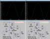
This is a basic FM transmitter circuit. I made lots of basic transmitters as an experiment. This one has class-C driver and class-c output amplifiers made by T3 and T4. T1 is an oscillator but I think T2 is not 'RF amplifier'. T3 is class c amp so I think T2 is related to impedance matching stage necessary for T3 amp, Isn't it?
Circuit and details are here- https://pira.cz/entx2.htm

If it is impedance matching stage, then should we need to use UHF transistor- 'BFR91A' as designer? What happens if I used 2N4401 (Ic=600mA) VHF transistor? 2N4401 has 250MHz fT. I think I can use, can't I?
 

Attachments

  • Pira 3watt.gif
    Pira 3watt.gif
    8.7 KB · Views: 3,523
It's a simple amplifier, both boosting the output of the oscillator, and also isolating it from the following stages - including the PLL circuit, which will probably require a higher level than from the oscillator direct.

Try the transistor and see, but it's not got a very high fT so it's gain is likely to be low.
 
When a transistor has an fT at 250MHz like a 2N4401 then at 250MHz its AC current gain is 1 like a piece of wire. At 125MHz then its AC current gain is only 2 times.
When a transistor has an fT at 6GHz like a BFR91A then at 3GHz its AC current gain is 2, at 750kHz its AC current gain is 8 and at 93.75MHz its AC current gain is 64 times.
 
But is it an RF amplifier where transistor biased with only resistors?
 
But is it an RF amplifier where transistor biased with only resistors?
If a transistor does not have much current gain at a certain frequency then it does not amplify much.
A class-A amplifier is biased, a class-C amplifier is not biased.
T2 is biased with R10 as a class-A amplifier. T3 and T4 are not biased so they are class-C amplifiers.
 
Then I think if I used-

T1- 2N3904
T2- 2N4401
T3- 2N2219
T4- 2N3866 or 2N3553

Then this 3 watt machine will produce just around 1 watt due to low gain transistors, isn't it?
 
The 2N2219 is very old and is difficult to cool. I would never use one.
I did not look at the datasheets for the 2N3866 and 2N3553 because a high power FM transmitter is illegal without a licence.
 
When a transistor has an fT at 6GHz like a BFR91A then at 3GHz its AC current gain is 2, at 750kHz its AC current gain is 8 and at 93.75MHz its AC current gain is 64 times.

then what happens with S9018 transistor (lets say transistor as a Q3 on Mod-4). But S9018 has very low Ic and TPD. But it has 1.1GHz fT. Can we get any benifits of S9018 on FM Tx?
 
The S9018 transistor has low hFE. It will operate partially in class-C instead of class-A unless it has more bias current. There is a suffix letter that lists its range of hFE.
When it is biased correctly then its high amplification will probably cause it to over-heat and be destroyed.

Q3 in my Mod-4 transmitter is a 2N3904 that gets warm. It produces a fairly high output power.
 
Hi again after 14 months in the thread,

Yesterday I bought 10 pieces of S9018 at $0.5. These were in reel so I thought these are not fake. To compare, I scrapped one S9018 from a FM receiver and measured hFE 147. Then measured new one I bought and got just hFE 97.

And now basic question about hFE vs hfe- Can we say more DC current gain transistor has more AC gain too? Can we say 147 hFE transistor can amplify more AC signal than 97 hFE transistor can?
 
Did you know that hFE is DC current gain and hfe is AC current gain? They have only a small effect on voltage gain.
The one with a higher hfe will deliver more signal to a lower impedance if it has the same input power as one with a lower hfe.

Here is a simulation using a medium gain BC547B and a high gain BC547C. The numbers are from the datasheet so I hope the simulation software is accurate. The DC is shifted a little due to the different hFE but their amplification is almost the same.
The signals are distorted because the output levels are fairly high and there is no negative feedback.

EDIT: The outputs are the collectors.
 

Attachments

  • transistor hFE and hfe.png
    transistor hFE and hfe.png
    41.1 KB · Views: 682
AG, I understand it is measured at the collector. Right?
 
It's a simple amplifier, both boosting the output of the oscillator, and also isolating it from the following stages - including the PLL circuit, which will probably require a higher level than from the oscillator direct.

Try the transistor and see, but it's not got a very high fT so it's gain is likely to be low.

I have assembled the same circuit and with different transistor, C829 or C930 and it works well. As you mentioned the purpose of this transistor is to give isolation so that it keep the stability of the socilator. In my case i combined a PLL circuit with selector switch for required frequency.
 
Status
Not open for further replies.

Latest threads

New Articles From Microcontroller Tips

Back
Top