Gasboss775
Member
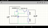
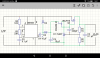
I built a simple voltage regulator, see attached, using a tl431 fed by a jfet wired as a current source and an npn buffer transistor.
I carried measurements of output resistance using the formula; Rout = ∆V/∆I. With loads between 0 and 125mA the output resistance was in fact negative, that is the output voltage actually increased ( albeit marginally ) as more current was drawn. Above 125mA it started to behave as would've been expected, that is a drop in output voltage under increasing current draw.
Can anyone explain this behaviour? I'm concerned that negative resistance could cause spurious oscillations.


 Good thing you checked out before her boyfriend came back.