godatguitar
New Member
Hi All
I am using a ULN 2803 to control 2 stepper motors, and the input to the IC is directly from an I/O port on an 8051 microcontroller.
The stepper motors are 24V, and "apparently" need 800mA each to operate. Does this sound correct? And is this safe with the ULN2803?
Basically, as I am aware the output is inverted, so to turn a coil from a motor on I apply a logic 0 to the corresponding input pin on the 2803.
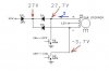
Also, the circuits I have seen use a Zener diode on the power input to the uln2803, usually slightly higher voltage than the motors require. Apparently this protects back emf? Is this right? Basically I have a 27V, 1.3W zener diode, and i do not want to blow the IC up with too large a current or something.
Any help would be great.
Cheers guys
Paul
I am using a ULN 2803 to control 2 stepper motors, and the input to the IC is directly from an I/O port on an 8051 microcontroller.
The stepper motors are 24V, and "apparently" need 800mA each to operate. Does this sound correct? And is this safe with the ULN2803?
Basically, as I am aware the output is inverted, so to turn a coil from a motor on I apply a logic 0 to the corresponding input pin on the 2803.
Also, the circuits I have seen use a Zener diode on the power input to the uln2803, usually slightly higher voltage than the motors require. Apparently this protects back emf? Is this right? Basically I have a 27V, 1.3W zener diode, and i do not want to blow the IC up with too large a current or something.
Any help would be great.
Cheers guys
Paul