Continue to Site

Welcome to our site!

Electro Tech is an online community (with over 170,000 members) who enjoy talking about and building electronic circuits, projects and gadgets. To participate you need to register. Registration is free. Click here to register now.

  • Welcome to our site! Electro Tech is an online community (with over 170,000 members) who enjoy talking about and building electronic circuits, projects and gadgets. To participate you need to register. Registration is free. Click here to register now.

UART Question

Status
Not open for further replies.

YAN-1

New Member
Hello. I want to interface an electronic compass that uses a UART module to a 16F877. However, the compass can be either supplied as it is on a PCB with the RC, TX, GND,.... pins available for attachment (welding), or I can get it with an RS232 port attached to it so that I can get an RS232 cable. I am not sure how to interface it in either way. Which is a better option?? In the second option, I'll attach an RS232 cable to the port, strip the wires, and solder them to the PIC pins?! And in the first option, I weld the compass pins directly to the PIC? Please help. Thanks.
 
YAN-1 said:
Hello. I want to interface an electronic compass that uses a UART module to a 16F877. However, the compass can be either supplied as it is on a PCB with the RC, TX, GND,.... pins available for attachment (welding), or I can get it with an RS232 port attached to it so that I can get an RS232 cable. I am not sure how to interface it in either way. Which is a better option?? In the second option, I'll attach an RS232 cable to the port, strip the wires, and solder them to the PIC pins?! And in the first option, I weld the compass pins directly to the PIC? Please help. Thanks.

For a start you don't "weld" anything, it's all soldered!.

Without reading the full spec I'm presuming that first option has TTL (5V) I/O levels, and would connect directly to the PIC pins?. The second option presumably adds a MAX232 converter, and you would need an extra MAX232 (or something similar) to convert back to feed the PIC.

So from the information you've given, I would suggest the first option is by far the best.

For PIC serial interfacing, check my tutorials!.
 
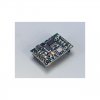
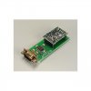
Well, the datasheets say that the UART pins are 5V CMOS compatible. Here is a picture of the compass with and without the RS232 port. I have also attached the dataheets. Please view them and help. How do I connect the pins directly to the PIC? And in the RS232 case, why would I need a MAX? Isn't the MAX needed when I am communicating with the serial port of the PC? But in this case, I don't have voltage levels to change, do I? :? HELP!
 

Attachments

  • hmr32003300_860.pdf
    167.5 KB · Views: 224
  • hmr3300-d00-232.jpg
    hmr3300-d00-232.jpg
    93 KB · Views: 698
  • hmr3300-no_rs232.jpg
    hmr3300-no_rs232.jpg
    98.4 KB · Views: 706
YAN-1 said:
Well, the datasheets say that the UART pins are 5V CMOS compatible. Here is a picture of the compass with and without the RS232 port. I have also attached the dataheets. Please view them and help. How do I connect the pins directly to the PIC? And in the RS232 case, why would I need a MAX? Isn't the MAX needed when I am communicating with the serial port of the PC? But in this case, I don't have voltage levels to change, do I? :? HELP!

The bottom picture, if you look between the socket and the compass board, has a surface mount chip fitted - this will be a MAX232 type chip, which converts from TTL to RS232.

So the output from that socket will be at RS232 levels, so you would need a second MAX232 at the PIC, to convert it back down to TTL levels. Far better (as I said before) to buy the cheaper (non-RS232) one, which will connect directly to the PIC pins.
 
Well ok. But what is the process by which I connect the pins to the PIC?! I really have little experience with soldering or other connecting processes. And another question please: will this compass be compatible with te PIC in the first place? Can you please take a quick look at the datasheets? Thanks a lot.
 
The compass pins are 5 V CMOS and so are the PIC 16F877 pins. Other than that, the UART module is a standard thing and there should be no problems?
 
YAN-1 said:
Well ok. But what is the process by which I connect the pins to the PIC?! I really have little experience with soldering or other connecting processes. And another question please: will this compass be compatible with te PIC in the first place? Can you please take a quick look at the datasheets? Thanks a lot.

It looks fine for connecting to a PIC, you should use it in UART mode, and set to use an external 5V supply - then connect four pins to the PIC circuit, GD - pin 7 (to 0V on the PIC - Vss), +5V - pin 6 (to 5V on the PIC - Vdd), TX - pin 2 (to serial in on the PIC - RC7), RX - pin 3 (to serial out on the PIC - RC6).

My RS232 tutorial at should provide all you need to do the interfacing. I would suggest you use the hardware USART in the 877, and I've given the required pins above. Tutorial 7.7a uses the hardware USART in the 876/7, but you will have to set the speed accordingly, the compass uses 19600 baud by default, and the tutorial uses 9600 baud - in only requires one value altering, and it's listed in the 877 datasheet.

You then need to write a program to control the compass, and to handle the data it supplies, I notice the first thing it does is send it's model and revision ID's.

If you care to send me a compass module I'll help you get it going, and probably do a tutorial on it? - but I suspect they are fairly expensive :cry:
 
Thanks a lot. I think it should be fairly easy with the datsheets and the tutorials available. Unfortunately, the compass costs $400 and I still haven't ordered it. I just wanted to see if it works in the first place before paying! I really appreciate your help. It is most useful. If we win the first place in the projects competition, I will be happy to buy one with the prize money just for your tutorial 8)
 
YAN-1 said:
Unfortunately, the compass costs $400 and I still haven't ordered it.

That's what I figured!.

You might consider getting the RS232 version, from the look of it you can simply unplug the compass module from the RS232 board. This would allow you to connect it via the RS232 board to evaluate your ideas on the PC, then remove the module from the RS232 board and write a PIC program to do the same thing!. Obviously use a socket for the module on your PIC board as well, so you can swap it backwards and forwards.

The inital evaluation and program design will be much faster to do on the PC - and I wouldn't expect the RS232 board to add too much to the cost of the compass?.

I've used this technique in the past (for developing a PIC based OSD board), initially I used the parallel port of my PC to control it, once I'd got everything figured out I then swapped to using a PIC instead. Obviously the code isn't anything similar, BUT the data transfer required is IDENTICAL - and that's where it helps!.
 
Hmmm. Good idea. The RS232 port adds around $50. I'll look into it. It's just that, believe it or not, I think it'll be easier for me to interface it directly to the PIC than to the PC first because the latter would require some sort of a VB or Visual C program to read from the serial port, whereas the UART module on the PIC is easier for me! Anyways, if the compass can be connected to the PIC without the RS232 port, then that's what I think I'm doing. I don't think I'll get the RS232 one. Thanks a lot.
 
YAN-1 said:
Hmmm. Good idea. The RS232 port adds around $50. I'll look into it. It's just that, believe it or not, I think it'll be easier for me to interface it directly to the PIC than to the PC first because the latter would require some sort of a VB or Visual C program to read from the serial port.

From what I read the compass just outputs plain ASCII, so you could use HyperTerminal on the PC to display it's output and to send commands to it.

But $50 extra is way over the top, perhaps $10 would be more like it?.

Certainly if it's $50 extra I wouldn't bother!.
 
Hehehe. Well, even though the project is being funded, we are running on a tight budget and I think we will need every dollar we've got! And besides, I don't trust myself to use the RS232 port, then simply 'remove' the compass without damaging it! By the way, I am still having some trouble trying to imagine how exactly will I connect the compass pins to the PIC. I mean I know which pins connect to which pins, but I'm confused about the connection process itself. Suppose I have the compass infront of me with the pins pointing out of its PCB, how do I go from there to the PIC pins?! :oops:
 
YAN-1 said:
Hehehe. Well, even though the project is being funded, we are running on a tight budget and I think we will need every dollar we've got! And besides, I don't trust myself to use the RS232 port, then simply 'remove' the compass without damaging it! By the way, I am still having some trouble trying to imagine how exactly will I connect the compass pins to the PIC. I mean I know which pins connect to which pins, but I'm confused about the connection process itself. Suppose I have the compass infront of me with the pins pointing out of its PCB, how do I go from there to the PIC pins?! :oops:

You use a board, either a PCB or something like veroboard, fit sockets for both the compass module and the PIC to plug in to.
 
Status
Not open for further replies.

Latest threads

New Articles From Microcontroller Tips

Back
Top