Continue to Site

Welcome to our site!

Electro Tech is an online community (with over 170,000 members) who enjoy talking about and building electronic circuits, projects and gadgets. To participate you need to register. Registration is free. Click here to register now.

  • Welcome to our site! Electro Tech is an online community (with over 170,000 members) who enjoy talking about and building electronic circuits, projects and gadgets. To participate you need to register. Registration is free. Click here to register now.

Tyre Pressure Meter Interfacing

Status
Not open for further replies.

dougy83

Well-Known Member
Most Helpful Member
Hi All,

Does anyone know how to get the pressure data from one of these cheap tyre pressure sensors?
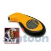
ME18B7_SO.jpg

The sensor is a bare silicon die on the PCB inside the device. There's a number of test points on the PCB, and the only one that appears to be useful is one that has pulses that alternate in amplitude. There are other TPs that have a stream of small pulses. All pulses on different TPs are in sync.
altpulse1.png

I captured the level of the pulses and coded them as '1' for a large pulse and '0' for a small pulse.
Code:
0101010101010101010101010101010101011101011101010101011101011101010111011111010101111111011111010101111101011111111111111111111111111111111111111111111111111111111111111111111111111111111111111111111111111111111111111111111111111111111111111111111111111111111111111111111111111111111111111111111101110111111101010111011111011101011111011111111111111111111101010101011101010101010101010101010101010101010101010101010101010101010101010
I further coded this so that "01" becomes '0' and "11" becomes '1' in the hope that this turned up some sensible information.
Code:
000000000000000000100100000100100010110001110110001100111111111111111111111111111111111111111111111111111111111111111111111111111111111111111111111101011100010110100110111111111100000100000000000000000000000000000000#
The above is recorded over 25 seconds; when the device is started, there is no pressure applied to the sensor (which causes the string of "01010101"s). Then a pressure of 15-30 psi is applied, and may be removed before the end of the recording.

I was too dumb to get any meaningful info from the data (which I assume has pressure information in it).

Anyone else up for the challenge?
 
Looking at your 0 and 1 data, I think the first thing to do is quantify the ratio of 0:1 bits vs pressure.

So i would hook the sensor up to known reference pressures, and count the ratio of those bits (as a percentage, like you would do for a duty cycle). Then quickly chart it and if there is a linear slope of pressure:duty you are home free, all you need to do is scale and offset it to get real PSI from the duty cycle.
 
Thanks for the replies.

I don't have a decent camera on hand, so some very poor photos are attached.
backpresspcb.jpgfrontpresspcb.jpg

Mr RB, the pulse rate is 20 Hz and every second pulse is high (10 Hz bitrate equivalent). This means that for 99.5 PSI (from "specs" linked below) you'd need a minimum of 200 counts, which would take 20 seconds to receive a single reading. While I agree with you that I need to record the actual displayed pressure, I don't think the duty cycle / number of pulses high will deliver this information.

"Specs" for the device are here **broken link removed**
 
I wish you had clearer photos. :)

The only easy option is to decode the signal coming out of the sensor, but if the bitstream is too slow that won't give you enough resolution. Do we know what is happening at the sensor? There seem to be a lot of wires (tracks) going from the micro to the sensor.

The micro might be doing some type of Sigma Delta modulation of the sensor, to get an average reading that matches the pressure. If so you can get the average from the ratio of 1 to 0 bits (like I said before) but as you said since the frequency is so low you need to average at least a few seconds to get a low resolution reading.

How long does it take to display a pressure reading? That info will help, as will info on the actual wiring to the sensor.
 
Here are some better photos.
fullsm.jpgcp.jpg
Appears that the sensor is wired as a 4 terminal device. The response rate seems to be less than half a second, so that would kinda rule out digital coding and might lead one to believe that the signal is actually analogue. The sensor could be a bridge sensor, with the micro is providing pulses (reduce power consumption) of supply power for 2ms (sufficient time for ADC to acquire a stable signal).

I didn't see any apparently valid value between any two test points, but I probably made a mistake or simply the signal is too small to see against the noise of the DSO2250 oscilloscope. This, and the fact that the pulse stream appeared to be encoded, made me believe it possible for digital encoding.
 
I guess that might mean TP7 could be the [dual] drive negative connection, TP6 the positive drive, and TP8 and TP5 are the bridge outputs...

ref Figure 1 of https://www.maximintegrated.com/app-notes/index.mvp/id/871 with the extraneous connection removed

EDIT: Seems to be a possibility. Measured peak differential voltage with 0, 10-15 and ~30 psi (based on bike pump gauge, not digital gauge) are 127, 134 and 140 mV respectively. So it's around 433 uV/psi.
0psi ambient.png 30 psi ~30psi.png
 
Last edited:
Looks a little bit like a motorola mpx series pressure sensor, which are analogue, they have 2 pins for power and the other 2 are differential o/p's, + and -, you can connect these to a differential op amp circuit to amplify the o/p.
 
Yeah I never thought it was a digital sensor, I thought it was a pulsed conversion process with an analogue sensor.

It's a good bet that it is an analogue bridge sensor as you and dr_pepper thought. Now of course if you interface to just the sensor then the rest of the unit can be discarded, it becomes a $4 pressure sensor.

The last pressure sensor I used was one of the new breed that outputs 0-5v DC linearly for it's pressure range of 0-10 PSI. Much much nicer to interface to ADC than a strain bridge type. And it was calibrated and only about $16 if I remember right, so a cheaply made uncalibrated sensor at $4 is not great value (especially if you have to add an opamp etc).
 
Yes its a cheap source of air pressure sensors.
I wonder how the ones you find in vehicles work, a popular gimick is a car dash that tells you all the tyre pressures, makes me wonder if theres one of these in each wheel with a battery, or maybe a rfid type interface similar to the transponder in ignition keys.
 
The last pressure sensor I used was one of the new breed that outputs 0-5v DC linearly for it's pressure range of 0-10 PSI. Much much nicer to interface to ADC than a strain bridge type. And it was calibrated and only about $16 if I remember right, so a cheaply made uncalibrated sensor at $4 is not great value (especially if you have to add an opamp etc).
Yes, that does sound easier to interface. The bridge is fine with me as well. Thanks for your input.

Yes its a cheap source of air pressure sensors.
I wonder how the ones you find in vehicles work, a popular gimick is a car dash that tells you all the tyre pressures, makes me wonder if theres one of these in each wheel with a battery, or maybe a rfid type interface similar to the transponder in ignition keys.
Yes, there's one in each wheel and the transmit wirelessly. Search for "tire pressure monitoring system" in google and you'll get a bunch of results, including application notes from Microchip. You can get aftermarket ones too if you wanted to retro fit some; some mount inside the tyre, while others mount on the valve stem.
 
I agree its a sales gimmick that is actually usefull.
I run sheds so I've never had such a thing.
 
Status
Not open for further replies.

Latest threads

Back
Top