Continue to Site

Welcome to our site!

Electro Tech is an online community (with over 170,000 members) who enjoy talking about and building electronic circuits, projects and gadgets. To participate you need to register. Registration is free. Click here to register now.

  • Welcome to our site! Electro Tech is an online community (with over 170,000 members) who enjoy talking about and building electronic circuits, projects and gadgets. To participate you need to register. Registration is free. Click here to register now.

Two basic questions about LM211

Status
Not open for further replies.

nyoo

Member
Hi,

As a beginner, I'm trying to merge a few simple schematics, and have a couple of basic questions about the LM211 comparator.

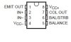
For the Texas Instruments version of the LM211, there are two pins, "col out" and "emit out". See attached schematic and pin-out drawing. I picked "col out". Was that right? In either case, could someone please explain why the two options?

Also, in a previous discussion of LM211, a forum advisor suggested that you could drive a relay directly with LM211's 50 mA output. But I'm told the pull-up resistor is absolutely required. Could someone please resolve that conflict?

Thanks for your help.
 

Attachments

  • lm211 diff therm.JPG
    lm211 diff therm.JPG
    18.2 KB · Views: 581
  • LM211 pins.JPG
    LM211 pins.JPG
    6.7 KB · Views: 265
How much current does the relay use?

If it's under 50mA then you can drive the relay directly.

Think about it, a pull-up resistor just connects the output to the positive rail. A relay would behave just like a pull-up resistor.

For future reference, please draw comparators using the proper symbol or at least put pin numbers on the schematic otherwise it's extremely hard to read.
**broken link removed**
 
Using the COL output (pin 7) to drive the 2N3906 or the relay is OK. But also note that all of the applications that use the COL output also connect the EMIT (pin 1) to ground or (-).

[You won't usually find a separate ground pin for the output transistor.]

In your diagram, the 1K resistor serves as the pull up resistor.
 
Connected EMIT (pin 1) to ground.
Took out the 2N3906 and the pull-up resistor.
Still don't really understand source vs. sink, so I'm guessing.

Please could someone approve or improve the revised schematic?

Thanks for your help.
 

Attachments

  • lm211 diff therm2.JPG
    lm211 diff therm2.JPG
    16.3 KB · Views: 351
Still don't really understand source vs. sink, so I'm guessing.
Source means the current flow is out from the pin to a grounded load (it's sourcing current). Sink means the current flow is into the pin from a load connected to a positive voltage (it's sinking current). For example the collector of an NPN transistor with it's emitter grounded would be a sink.
 
Connected EMIT (pin 1) to ground.
Took out the 2N3906 and the pull-up resistor.
Still don't really understand source vs. sink, so I'm guessing.

Please could someone approve or improve the revised schematic?

Thanks for your help.
That will be fine providing the relay uses ≤50mA.

As mentioned above, the LM211 can sink current be it can't source it. If you wanted to connect the relay from the output to 0V then I would have said no because you would be trying to make it source when it can only sink.
 
I'm using an 833H relay. The 12VDC version has a rated current of 30 mA.

Thanks for all your help.
 
That's gine

I love the little LM311 for this.

It's my favourite comparator for simple circuits like this.

How many other comparators can directly drive a small relay?
 
Last edited:
Status
Not open for further replies.

New Articles From Microcontroller Tips

Back
Top