hello all!
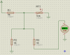
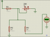
i am working with a temp measurement circuit using a 10k NTC thermistor. i will post a pic of what i am doing with this circuit, but my problem is that i am not getting the voltage i expect to my processor.
see attatched diagram
any help is wonderful - is there a formula i need to calculate the expected voltage to my processor?
thanks a ton guys!!
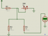
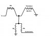
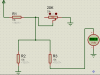
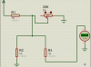
 Guess I should have taken more time or redrawn it.