Continue to Site

Welcome to our site!

Electro Tech is an online community (with over 170,000 members) who enjoy talking about and building electronic circuits, projects and gadgets. To participate you need to register. Registration is free. Click here to register now.

  • Welcome to our site! Electro Tech is an online community (with over 170,000 members) who enjoy talking about and building electronic circuits, projects and gadgets. To participate you need to register. Registration is free. Click here to register now.

Tweaking li-ion protection pcb for 3.0V low voltage cut-off

Status
Not open for further replies.

fedcas

New Member
I’ve been googling for this for a while. I have a - poorly designed - circuit (it's a step-up regulator for a usb powerbank, this one actually **broken link removed** ) which has no low voltage cut-off so I want to add one. Actually i'm running it with a protected 18650, but i still want an external cutoff because:

1) 18650 protection board cutoff kicks in at 2.5-2.4V which i think is definitely too low for daily use
2) a protection circuit should be the last resort in case something goes wrong, i don’t think it should be used on a regular basis (and i don’t know how reliable they are)
3) battery integrated overdischarge protection must not prevent the battery from operating correctly in any operating scenario, either under low or high loads... that means the cutoff is set to a very low value to avoid that with high discharge currents (high voltage sag) it kicks in before the battery has discharged completely


It looks like a simple and common problem, but apparently the solution is not as simple. I've found many threads on forums and many pages... a lot of talks, hints and good ideas, very few tested circuits though... but here's a couple of interesting links:
http://hackaday.com/2011/12/01/from-the-readers-low-battery-cutoff-solutions/ (read the comments as well)
**broken link removed**

many of those circuits require microcontrollers, which i don't want to use, and the simple ones have all have some drawbacks that made me discard them. So what is left are dedicated protection boards.

But again, a couple suggested in the blog post linked above http://www.all-battery.com/1S_Li-Ion.aspx looks great having the 2.9-3.0v cutoff, but that shop is only a solution for people living in the us. As i live in europe i’ve had a look to protection pcbs on ebay and aliexpress, cheap and easy, but i can only find circuits with cutoff at 2.5v or 2.4v while something around 3.0v is needed… if anyone finds something it would be much appreciated


SO:
here’s my idea, i'd like to have some opinions as i have just a very basic electronic knowledge:
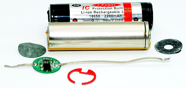
Since finding a board programmed for 3.0v cutoff seems too complicated, i thought to tweak the common 2.5 cutoff board that i can easily steal from a any 18650 i have laying around or just buy a bunch of them on aliexpress for as low as 1$ shipped or less:

**broken link removed**


Then I can use a voltage divider with just 2 resistors to set the kick in voltage wherever i want, instead of connecting the board reference directly to the positive electrode… of course resistors in the Kohm-Mohm range would be needed to avoid battery drain, and it’s probably a good idea to add a capacitor when using so high resistor values for the reason explained here http://jeelabs.org/2013/05/16/measuring-the-battery-without-draining-it/ (i don’t know much about microcontrollers, but i guess this high impedance thing might be a common issue).

Any suggestion/better idea?
 
Last edited:
I have seen videos of 18650 Lithium cells on U-tube with fake protection circuits that are simply a photo of a protection circuit. They look REAL! Have you found any?
 
Hi,

Low voltage protection is not hard to add to a circuit if it does not have to be super small. High current protection is harder to add because that means current sensing, and current sensing is harder to do than voltage sensing.

A simple low voltage protection circuit is made from a comparator chip and low Rds MOSFET, and a few 1/4 watt resistors, and maybe a voltage reference IC chip that regulates at close to 1.24 volts.

The idea is to power the reference IC with a small current, low enough such that it does not reduce the charge significantly over time. This would be maybe 100ua. That 1.24v is used as a reference, and the battery voltage is divided down to close to 1.24v when the cell reaches about (say) 3.0 volts (the cutout point). This requires two resistors in the hundreds of K value, or at least 100k or so.

The resistor divider and reference voltage (1.24v) is are connected to the input of the comparator. The comparator output goes low when the divider voltage goes lower than the reference voltage. The comparator output then switches off the MOSFET, and the circuit to the load gets turned off.

That is the basic low voltage cutout circuit. To do over-current is harder because the current itself has to be sensed through a very low value resistor like 10mOhms, and then that voltage has to be amplified. If you can get away without this it would be good, but if not then you'd need a circuit for that too. We can design one here or find one on the web and modify it.

One thing i like about doing our own circuit is that then we know ALL the parts that went into it, so we can be sure it will work well, and we can also get more parts if we need them and build more of them.
 
I have seen videos of 18650 Lithium cells on U-tube with fake protection circuits that are simply a photo of a protection circuit. They look REAL! Have you found any?

I've heard of that (never found one luckily... i think is important to buy well-known models of li-ion cells. I personally use NCR18650B from Soshine and Keepower that are not very expensive yet have a good reputation and the protections have been tested)

btw here is a couple of interesting articles:

https://www.lygte-info.dk/info/battery protection UK.html

https://lygte-info.dk/info/DischargeProtectionTest UK.html
 
Hi,

Low voltage protection is not hard to add to a circuit if it does not have to be super small. High current protection is harder to add because that means current sensing, and current sensing is harder to do than voltage sensing.

A simple low voltage protection circuit is made from a comparator chip and low Rds MOSFET, and a few 1/4 watt resistors, and maybe a voltage reference IC chip that regulates at close to 1.24 volts.

I also imagined something like that, and i since there should be plenty of people that want to run any kind of circuit or load from a battery and needed a low voltage cutoff, i thought there should be plenty of standard and tested circuits on the internet... but seems like is not like that, i'm quite surprised.


That is the basic low voltage cutout circuit. To do over-current is harder because the current itself has to be sensed through a very low value resistor like 10mOhms, and then that voltage has to be amplified. If you can get away without this it would be good, but if not then you'd need a circuit for that too. We can design one here or find one on the web and modify it.

i don't need over current protection because it's not something that is going to happen during normale use, unlike overdischarge which is going to happen every time, so redundancy is not required and in case of malfunctioning the overcurrent/shortcircuit protection of the cell should be ok.

One thing i like about doing our own circuit is that then we know ALL the parts that went into it, so we can be sure it will work well, and we can also get more parts if we need them and build more of them.

uhm... so you are basically suggesting to build a protection circuit similar to the ready available ones i have linked, but with no strict size limit and using a comparator instead of the microcontroller because only the low voltage protection is needed?

An important requirement that i want for that kind of circuit is - as you also suggested - that the operating resistance and the parasitic drain should be negligible. It's interesting to watch how ready made pcbs work from this point of view: here is a battery test comparator, if you choose the protected and non-protected version of the same Panasonic cell you can see how small the voltage drop and the capacity loss is even under high loads:
https://lygte-info.dk/review/batteries2012/Common18650comparator.php

Do you think a self made circuit would wasily meet this requirements?


Also, I've seen you were also considering a voltage divider, so do you think my original idea of attaching a protection pcb to a voltage divider should work well or there might be some drawbacks? (assuming the protection circuit itself is working properly)

thanks :)
 
Do some people use a Lithium battery protection circuit as a battery charger? It would disconnect the charger when the battery is almost fully charged. I think you simply must provide a series resistor to limit the charging current.
 
I also imagined something like that, and i since there should be plenty of people that want to run any kind of circuit or load from a battery and needed a low voltage cutoff, i thought there should be plenty of standard and tested circuits on the internet... but seems like is not like that, i'm quite surprised.


i don't need over current protection because it's not something that is going to happen during normale use, unlike overdischarge which is going to happen every time, so redundancy is not required and in case of malfunctioning the overcurrent/shortcircuit protection of the cell should be ok.


uhm... so you are basically suggesting to build a protection circuit similar to the ready available ones i have linked, but with no strict size limit and using a comparator instead of the microcontroller because only the low voltage protection is needed?

An important requirement that i want for that kind of circuit is - as you also suggested - that the operating resistance and the parasitic drain should be negligible. It's interesting to watch how ready made pcbs work from this point of view: here is a battery test comparator, if you choose the protected and non-protected version of the same Panasonic cell you can see how small the voltage drop and the capacity loss is even under high loads:
https://lygte-info.dk/review/batteries2012/Common18650comparator.php

Do you think a self made circuit would wasily meet this requirements?


Also, I've seen you were also considering a voltage divider, so do you think my original idea of attaching a protection pcb to a voltage divider should work well or there might be some drawbacks? (assuming the protection circuit itself is working properly)

thanks :)


Hi,

Interesting sight with the battery tests. I'll have to look at that some more.

Yes, a comparator and voltage divider, plus reference diode. The voltage divider is super simple, just two resistors, maybe another resistor for hysteresis. All 1/4 watt but 1/8 watt or SMD would work too because we will use high value resistors.
The main ingredient to make this thing work with little voltage drop is the MOSFET. The better the MOSFET, the lower the drop, more or less. We want an over sized MOSFET so that the drop is minimal. That means a 20 amp device, 50 amp device, etc., that has a series resistance of around 0.050 ohms or better. 0.020 ohm would be nice. These are not that hard to find these days.

A quick basic parts list:
1. Voltage reference diode, 1.25v type.
2. Two resistors for the voltage divider, one for hysteresis.
3. Comparator, like LM339, LM393, or similar or maybe a low voltage type, possibly with pullup resistor.
4. Maybe a 0.1uf cap across the comparator chip, maybe one across the lower voltage divider resistor.
5. Low Rds MOSFET, with logic type driven gate (low voltage gate).

How much current do you need to run with this thing? That dictates the MOSFET rating, or we could just go with a higher current MOSFET so it works at almost any reasonable current.
 
do you think my original idea of attaching a protection pcb to a voltage divider should work well or there might be some drawbacks?
From the link, it looks like the protection pcb doesn't allow access to its internal switching-FET gate control, which I think you would need. So you'd still require an additional FET at least and would effectively just be using the pcb as a voltage reference.
How about the following circuit? I haven't built it, but simulation shows it should provide a switch-off trip point varying by no more than 0.2V over a temperature range of -20C to +40C.
LowBatteryTurnoff.gif
M2 should have a very low Vgs(th) (~1V); M1 should have a very low Rds(on) (milliOhms).
Battery drain is <3uA when 'on' and <5nA when 'off'.
It might need a small capacitor (or momentary switch) across M1 to 'kick start' it when first used.
 
Last edited:
How much current do you need to run with this thing? That dictates the MOSFET rating, or we could just go with a higher current MOSFET so it works at almost any reasonable current.

the maximum current from the battery is around 2A


From the link, it looks like the protection pcb doesn't allow access to its internal switching-FET gate control, which I think you would need. So you'd still require an additional FET at least and would effectively just be using the pcb as a voltage reference.

Here is a protected cell showing the protection pcb.
DSC_8575.jpg


The pcb is basically connected in series with the battery and has another connection (the long one) to the + electrode to get the voltage reading. So my idea is putting a voltage divider in between the + electrode and the voltage reading going to the pcb. It should work, right?

How about the following circuit? I haven't built it, but simulation shows it should provide a switch-off trip point varying by no more than 0.2V over a temperature range of -20C to +40C.
View attachment 90743
M2 should have a very low Vgs(th) (~1V); M1 should have a very low Rds(on) (milliOhms).
Battery drain is <3uA when 'on' and <5nA when 'off'.
It might need a small capacitor (or momentary switch) across M1 to 'kick start' it when first used.

thanks, but i have no idea whether it will suit my needs :p i should wait for other people commenting it ;)
 
the maximum current from the battery is around 2A


Here is a protected cell showing the protection pcb.
DSC_8575.jpg


The pcb is basically connected in series with the battery and has another connection (the long one) to the + electrode to get the voltage reading. So my idea is putting a voltage divider in between the + electrode and the voltage reading going to the pcb. It should work, right?


thanks, but i have no idea whether it will suit my needs :p i should wait for other people commenting it ;)


Hi,

Do you have a schematic? We can tell how to do it with a schematic, but without one it is only guessing. Where is the voltage sense point on the circuit.
 
the maximum current from the battery is around 2A


Here is a protected cell showing the protection pcb.
DSC_8575.jpg


The pcb is basically connected in series with the battery and has another connection (the long one) to the + electrode to get the voltage reading. So my idea is putting a voltage divider in between the + electrode and the voltage reading going to the pcb. It should work, right?


thanks, but i have no idea whether it will suit my needs :p i should wait for other people commenting it ;)

Your idea is good and it will work. Alternatively you can connect a PIN diode in series to the protection circuit. PIN diode forward voltage is only 0.4V + the 2.5V will give you 2.9V cut off. This way you don't wast current on voltage divider and it is more accurate. I guess that you realize that this change will also increase the max charge voltage cut off from 4.2V to 4.6V, over charge is dangerous too.
 
Last edited:
Hi,

Here are two circuits that can be used. Note that the comparator has to be a micro power type, and all the resistor values have to be highish like 100k or greater, but not too much greater.
The run time from a full charge based on a 2000mAhr cell can be estimated from:
Years=Iua/228

where
Iua is the current in microamperes, and
Years is the run time in years.

So for example, if the circuit draws 228ua then the run time is 1 year. If the circuit draws half that or 114ua then the run time is 2 years. So the idea is to keep the run current down as low as possible. With a micro controller this is easy because we can put it to sleep and then wake up, check, then go back to sleep again. With a purely analog circuit we have to find a micropower comparator like the LT1017 or the LT6703 (the LT6703 would even simplify one of these circuits as it has built in voltage reference).
 

Attachments

  • UnderVoltageProtection.gif
    UnderVoltageProtection.gif
    12.5 KB · Views: 699
Last edited:
Status
Not open for further replies.

New Articles From Microcontroller Tips

Back
Top