Continue to Site

Welcome to our site!

Electro Tech is an online community (with over 170,000 members) who enjoy talking about and building electronic circuits, projects and gadgets. To participate you need to register. Registration is free. Click here to register now.

  • Welcome to our site! Electro Tech is an online community (with over 170,000 members) who enjoy talking about and building electronic circuits, projects and gadgets. To participate you need to register. Registration is free. Click here to register now.

Tweaking a ramp pulse generator! Ahh!

Status
Not open for further replies.

winners

New Member
Hi team.

I am trying to build a simple, ramping, linear pulse generator which increases in current much faster than the time to decay for a self designed medical research project.

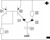
The circuit design is driving me insane! I need a steep rise and a slow decay and I know I need a capacitor for the pulse behaviour, a resistor to slow the decay time and perhaps pnp transistors to ensure a linear rise in current while charging the capacitor.

but..

how it all goes together puzzles me greatly! Especially where i should attach the outputs for the waveform.

Guys, how can i set up a circuit that gives me a sharp (hopefully linear) current rise and a slowed decay time?

ANY help would be MUCH appreciated!

with kind regards
michael.
 
To get a linear slope up you need to charge the capacitor from a constant current source, likewise, to get a linear slope down you need to discharge if through a constant current sink.

I seem to remember you can do this with a couple of opamps?, one as a comparator, the other charging and discharging the capacitor - with two different value charging resistors, connected in parallel with diodes in series - so one resistor is used for charging, and the other for discharging.

Here's a suitable circuit , you just need to replace Rt with two resistors in parallel, with a diode in series with each resistor (so one charges, and one discharges).
 
Thanks Nigel..just a couple more q's.. :eek:0

Thanks for your reply.. I understand what you mean with respect to a 'charging' and 'discharging' resistor-diode setup..but... won't placing even a small resistor before the capacitor (during the charging phase) create a sloping rise on the curve?

Perhaps it won't matter, but i found a different circuit (designed for a different purpose) that used two 'pnp transistors' to create an even charge flow to a capacitor and hence form a linear rise. Though i can't get my head around how or where to place a 'discharging resistor'. It seems everywhere i place one looks as though it will affect charging speed too.

Have any idea just how one could fix this setup?, or even if it will matter if an op amp could do the job for me anyway?

I do hope to run this pretty fast. In my final circuit, I hope to have a 555 timer, pulsing a counter, which enters a decoder, which sends a
signal into the circuit we're discussing now. (I need more than one of these firing just out of phase to each other hence the counter-de oder setup)

Would including another IC slow things down?

Thanks so much for helping me. I've been learning alot lately and do appreciate it.

Kind regards

Michael
 
Could anyone check this out to see if it will work how i've described above? In particular have i got R2 connected properly?

cheers team.. you rock.

Michael
 

Attachments

  • untitled-1_758.jpg
    untitled-1_758.jpg
    65.4 KB · Views: 742
Re: Thanks Nigel..just a couple more q's.. :eek:0

winners said:
Thanks for your reply.. I understand what you mean with respect to a 'charging' and 'discharging' resistor-diode setup..but... won't placing even a small resistor before the capacitor (during the charging phase) create a sloping rise on the curve?

You're not fitting a resistor in series with the capacitor, the two resistor/diode combination replaces Rt, which feeds into the opamp. The capacitor goes directly from the output directly back to the input.

Perhaps it won't matter, but i found a different circuit (designed for a different purpose) that used two 'pnp transistors' to create an even charge flow to a capacitor and hence form a linear rise. Though i can't get my head around how or where to place a 'discharging resistor'. It seems everywhere i place one looks as though it will affect charging speed too.

Have any idea just how one could fix this setup?, or even if it will matter if an op amp could do the job for me anyway?

You would need to switch the charging/discharging circuits in and out as they were needed.

I do hope to run this pretty fast. In my final circuit, I hope to have a 555 timer, pulsing a counter, which enters a decoder, which sends a
signal into the circuit we're discussing now. (I need more than one of these firing just out of phase to each other hence the counter-de oder setup)

Would including another IC slow things down?

How fast does it need to work? - most electronics work at the speed of light.
 
It isn't clear to me which slope ramp you want. Below is a schematic showing general schemes for generating either, along with waveforms. If you need specific modifications, post here.
 

Attachments

  • ramp_gen_waves.gif
    ramp_gen_waves.gif
    12.1 KB · Views: 450
  • ramp_gen.gif
    ramp_gen.gif
    12.2 KB · Views: 460
Russlk said:
Ron, are you using Switcher Cad? How do you rotate the resistors? I find the edit command to rotate but it is grayed out and I don't know how to select the component.
Yep, it's SwitcherCAD. I don't know what the grayed-out circular arrows are for. The one to the right, that looks like an "E" being laid on its side, is the rotate button. Yu can also go to Edit - Rotate, or you can use ctrl-R, which is what I almost always use.
 
Status
Not open for further replies.

Latest threads

New Articles From Microcontroller Tips

Back
Top