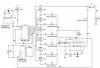
I'm trying to build this project, that will play the first line of the tune "Happy birthday to you". I want to use only 6 tones (frequencies) to play the tune.
The basic idea that I tried implementing is that, the 4093 IC produces pulses of a specific frequency (determined by C5 and R1). The frequency is supposed to be adjustable, so I'm using a potentiometer as R1.
The output from the 4093 pulse goes to the 4017 decade counter (5-stage johnson), the outputs of which are connected to a 555 timer. As each output of the decade counter goes high, the 555 timer (operating in astable mode), is to produce an output, the frequency of which will vary with the resistances (potentiometers) connected to the decade counter outputs. Therefore, by varying the potentiometers at the 4017 outputs, the frequency of the output (tones) at the 555 timer should change. And setting the resistances in sequence to produce specific frequencies should produce the tune. The hex inverter is used to reset the 555 timer, after giving gaps after the last tone played, and then the 9th output resets the 4017 to start the tune over again.
PROBLEMS:
So far, here's the trouble im having. The 4093 schmidt trigger nand gate isn't giving a pulse of consistent frequency. It seems to be varying between two frequencies. This appears to get fixed when i remove the ground connection from the Vss pin. Should I just remove the ground? Is that good for practical purposes when i make this circuit on the breadboard?
I dont seem to be getting any output at the 4017 counter and the 555 timer. I do get an output when i remove the ground from the Vss pin of the 4017 timer. However, its not the right output. THe frequencies don't change at the 555 timer as they should. Right now I have an 8 ohm resistor simulating the presence of an 8 ohm speaker. I have the potentiometers at the decade counter set to produce the following tones at the 555 timer output, giving the tune for the 1st line of "Happy birthday to you" (potentiometers should be set at 100%, as opposed to 50% as shown in diagram). I need potentiometers because i want to be able to change the tunes produced by
changing the output frequencies of the 555 timer.
Also, i'm not getting a square wave at the speaker. Its a very distored wave. Could be some speaker loading issue ?
Can anyone please guide me on what i'm doing wrong, and how I need to modify this circuit to get the results i want?
Here are the frequencies i'm using for the tune:
392 392 440 392 523 494 (Hz)
G G A G C1 B
"ha ppy birth day to you"
Any help will be greatly appreciated. Thanks !!
Oz
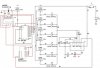
")
