Mike_2545
Super Moderator
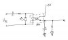
I have been working on a circuit to be able to tell a logic level device, i.e. micro controller, or other TTL device, whether a 120 vac circuit is actuated. I could use a transformer/power supply but would like to accomplish this with as few parts as possible.
I have sketched out what I think will work and but thought about running it by the group to get feedback.
Mike 2545
I have sketched out what I think will work and but thought about running it by the group to get feedback.
Mike 2545
")