Continue to Site

Welcome to our site!

Electro Tech is an online community (with over 170,000 members) who enjoy talking about and building electronic circuits, projects and gadgets. To participate you need to register. Registration is free. Click here to register now.

  • Welcome to our site! Electro Tech is an online community (with over 170,000 members) who enjoy talking about and building electronic circuits, projects and gadgets. To participate you need to register. Registration is free. Click here to register now.

Trying to understand Opto-Isolator!

Status
Not open for further replies.

drkidd22

Member
I know the basics of how an opto-isolator (opocoupler) should work, but I'm trying to get a better understanding about them, specially on the output side (transistor).

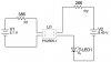
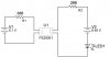
I have a PS2505-1 AC opto-isolator wired on my bread board as in the picture below. The current going in is 10.17mA measured with DMM. I'm using a cell phone charger as the voltage in on this side and it is stable at 5.11V. When I calculate this (5.11V - 1.17Vf)/(386Ohms) = 10.2mA mathematically which is pretty good and close to what I measured with the DMM, not a big deal here.

So now on to the photo-detector side. The LED has Vf = ~1.95V (RED standard LED). On this side I'm using a 9V battery and its output is ~ 8.45V. So I calculated (8.45V - 1.95Vf)/(266Ohms) = 24.4mA mathematically speaking unless I'm missing something, this would be Ic = 24.4mA right?

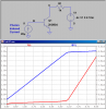
But my question is when I measure the current with the DMM on the transistor side. I only get 16.15mA, I'm out ~ 10mA, not too bad, but I want figure out what's going on. So what I did next was measure the voltage Between the Base and Collector (pin 3 and pin 4) and I get 2.18V. So I did (8.45)-(2.18Vce + 1.95Vf)/(266Ohms) = ~16.2mA. This works out. So the question is about the voltage that is present at the collector and the emitter. Looks like this is another voltage drop? does it vary depending on the Ic? Maybe I'm missing something from the datasheet and need to understand it.

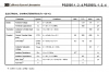
datasheets/ps2505.pdf

Any help with this will be appreciated.
thanks,
-Jose
 

Attachments

  • test.JPG
    test.JPG
    37.3 KB · Views: 491
Last edited:
So what I did next was measure the voltage Between the Base and Collector (pin 3 and pin 4) and I get 2.18V.
Emitter is pin 3, Collector is pin 4. If you measured Base to Collector on those pins, where did you measure Emitter to Collector?
 
First off, the circuit cant possibly work at all, since your led is reverse biased... ;)

You are thinking that the VCEsat of the NPN output side transistor is zero, which it most certainly is not! With 10ma of photo-emitter current, the device is only speced to sink 2mA to get a low VCE. If the VCE is 5V, then it will sink ~ 10mA. Look at the Current Transfer Ratio specs below:

Measure the voltage from collector (4) to emitter (3), I'll bet you see over 2V, which subtracts from the loop voltage.
 

Attachments

  • CTR.png
    CTR.png
    46.6 KB · Views: 309
First off, the circuit cant possibly work at all, since your led is reverse biased... ;)

You are thinking that the VCEsat of the NPN output side transistor is zero, which it most certainly is not! With 10ma of photo-emitter current, the device is only speced to sink 2mA to get a low VCE. If the VCE is 5V, then it will sink ~ 10mA. Look at the Current Transfer Ratio specs below:

Measure the voltage from collector (4) to emitter (3), I'll bet you see over 2V, which subtracts from the loop voltage.

Yeah, the circuit works. Just did the drawing wrong.
 

Attachments

  • test.JPG
    test.JPG
    37.4 KB · Views: 518
Yes, exactly right, that is my problem and I need to understand it.

To get a low VCEsat, the current through the collecter-emitter must be very low, like <2mA. You are forcing like 15mA, so that brings the NPN out of saturation. Dump the LED, and raise the collector resistor to ~4.7K and measure the VCE again. Now it will be ~0.2V, but you will only be sinking ~1.5mA.
 
Last edited:
Alternatively, you can try to lower R1 for more diode current (assuming your input has the capability to drive that much.) The graph on page 7 shows VCEsat for different values of current. I think you can get 10mA at VCE=.2V. That might make the IC more useful.
 
Last edited:
so does driving Vce over saturation affect the IC? How would I be able to calculate Vce mathematically, I think is is what I need to know to get my mind opened a little more
 
Ok, stare at this. I used a general purpose NPN which I'm using as a proxy for the NPN in your Opto-isolator. The base current is due to photons being converted to carriers in the base-emitter junction. As the Collector power supply is swept from 0 to 9V, note what happens to the collector voltage and current. While the collector current [same as I(R1)] is less than ~5.9mA, the transistor is "saturated"; forcing more than 6mA into the collector brings the transistor out of saturation, and forces the collector voltage higher...

In your original measurements, you happened to pick a collector current that the was to the right of the knee in the curve...
 

Attachments

  • Draft47.png
    Draft47.png
    26.6 KB · Views: 306
Thanks,

I understand your graph, pretty clear, but where in the data sheet shows that the transistor will go out of saturation after ~6mA into the collector and how will I go about calculating what the Vce will be after its out of saturation.

Do I use this:
VCE(sat) Collector-Emitter Saturation Voltage:

IC = 10 mA, IB = 1.0 mA 0.2V
IC = 50 mA, IB = 5.0 mA 0.3V
 
The 6mA knee in my simulation is not exactly in the same place as where it will be in your OptoIsolator; I'm just trying to show what happens when you ask the transistor to sink a current greater than the transistor is capable of sinking based on it's β and how much base current is flowing into it.
 
I get the understanding that giving a higher Ic will increase the Vce and this gets subtracted from the voltage loop. A higher Ic will cause it to get out of saturation and if I had a higher If I will get higher Ic. So my question is, does driving the Ic at 16mA as I have it cause any damage to the component or better yet, is this practical?

My head hurts already from trying to digest this.

Thanks for your help guys/girls.
 
so does driving Vce over saturation affect the IC? How would I be able to calculate Vce mathematically, I think is is what I need to know to get my mind opened a little more


The problem with calculating VCEsat is that there are variations between produced units, and is shown by the "Min" "Max" and "Typical" values on the datasheet for the Current Transfer Ratio parameter. But just as a simple example, assume the ratio is the "Typical" value of 300, then for Ib= 1mA, the collector current will try to make 300mA. Wether or not it actually gets to that value depends on if the transistor goes into saturation or not. Let's assume a 100 ohm collector resistor, and .2V as the typical VCEsat. Further assume VCC = 30V and no LED, just to make the calculations easy:

Vc = VCC - IC*RC = 30V - .3*100 => 0V.

Since the result is less than .2V, the transistor is in saturation, and VCE will be about .2V, the collecter current is then:

IC = (30 - .2)/100 = .298 Amps.

Now, if you want ~24mA, then come at the problem from the other angle:

.024 = (VCC - .2)/RC; and rearrange:

RC = (VCC - .2)/.024 => 1.2K - use closest standard value.

Check to qualify satruation condition:

VC = VCC - 1.2K*.3 = -.06; this result is < .2V, so saturation is satisfied. If it had not been, then vary the diode current to achieve it.

Now, since we used "typical"values for Current Ratio, you have to readjust, or "fudge" the numbers to account for unit vairability. Make sure your diode current gives you lots of margin. Just use good judgement here, and do some experimenting. Good luck :)
 
Last edited:
Status
Not open for further replies.

Latest threads

Back
Top