Continue to Site

Welcome to our site!

Electro Tech is an online community (with over 170,000 members) who enjoy talking about and building electronic circuits, projects and gadgets. To participate you need to register. Registration is free. Click here to register now.

  • Welcome to our site! Electro Tech is an online community (with over 170,000 members) who enjoy talking about and building electronic circuits, projects and gadgets. To participate you need to register. Registration is free. Click here to register now.

Trying to make a battery solar panel voltage controller

Status
Not open for further replies.

b.james

Member
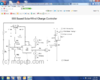
After a few different circuits which I could never quite understand I have settled on one at https://www.mdpub.com/555Controller/index.html.
It uses a 555timer so The flip flop on 1/3rd and 2/3rds voltage seems to work well.

I have some different needs though.
It is for 12 Volts . I want it to control 24 Volt systems with 30 volts in, and a 48 Volt system with a 80 Volt in ,from solar panel.
This circuit switches a relay on when it gets to its peak setting.
I want it to control a Mosfet and turn it off when it hits the top setting.
I am asking for help to firstly convert it to Mosfet switching off and also suggestions how I might change the circuit to control the higher voltages.The lm78l05 can only tale 15 volts max and a lm78l08 is limited to about 20V I think.so maybe a 317 which can take a 36V max might be used or maybe an entirely different approach might be warranted?
All help will be appreciated .Thanks
 
Is your 24V system two series-connected 12V batteries?
Is your 48V system four series-connected 12V batteries?
If so, unless your 12V batteries are exactly matched and remain so in use you would need separate controllers for each battery. Otherwise, the weakest battery in a series could be damaged.
 
Yes true but then each battery is a series of separate cells so its a problem of all series connection
The charge current passes through each in turn
I will ignore that for now and push on to make a controller for each system first
Does anyone else have any suggestions?
 
Do SLA batteries in series have to be exactly matched? It's often stated but as previously mentioned a 12V SLA battery is a series of 6 x 2V cells, how do they match these? Many medical devices use multiple 12V and 6V SLA batteries in series and I've never had to match them and never had a problem. (Granted they are usually the same type of battery purchased at the same time and probably from the same batch).
 
Here is one I think will work. You can use the LM317HV for the regulator. Make sure it is HV. I raised the voltage to 9 volts as the regulator is only specified for 60 volts input to output. So you will need to make your adjustments a little different than in the write up. 9/5 higher.

PS please don't tell my golf cart it's batteries can't be in series. I just bought new ones after 5 years. But they should be matched (same age and size) when you start. I've never gotten more than a few months more when I had to change one.
 

Attachments

  • solar.png
    solar.png
    147.4 KB · Views: 174
I had a lot of trouble understanding this . Is it possible to get a complete circuit showing where the 9 volts and other voltages are connected?
 
I'm not sure if I have made it better or worse, but lets see.

There are 2 parts: The 317 replaces your regulator (7805)
The rest replaces the relay Q! and Q2.
Hope the bigger picture helps.
 

Attachments

  • solar1.png
    solar1.png
    125.7 KB · Views: 211
  • solar2.png
    solar2.png
    342.2 KB · Views: 192
OK thanks that is more understandable I think so the 317HV can accept a higher input voltage and feed 9 Volts to the circuit .The Solar panel then feeds through a MOSFET to the battery with a blocking diode ?.
Pin3 goes high and turns the transistor 2n7002 on which turns the MOSFET on . Is that how it goes? or is the 3 pin going low that activates the rest ?
The 555 can take up to 15V input voltage so maybe I could adjust that to !5V
The solar panel is putting out 80Volts !
I have not used LTSpice for years but it seems that you have it set to 44V? or is that 60?
 
Last edited:
OK thanks that is more understandable I think so the 317HV can accept a higher input voltage and feed 9 Volts to the circuit .The Solar panel then feeds through a MOSFET to the battery with a blocking diode ?.
Yes, the 317HV can take 60 volts max from input to output. I figured maximum battery voltage of about 58.4. So there should be 10 volt safety margin.
Pin3 goes high and turns the transistor 2n7002 on which turns the MOSFET on . Is that how it goes? or is the 3 pin going low that activates the rest ?
Pin 3 going high turns it all on as it was before.
The 555 can take up to 15V input voltage so maybe I could adjust that to !5V
The solar panel is putting out 80Volts !
You could. Or maybe 10 volts would be an easy number to work with.
I missed the open circuit voltage of 80 volts on the panel. You will need to change the 7002 to a 100 volt FET-say an FQU13N10LTU.
[quote[I have not used LTSpice for years but it seems that you have it set to 44V? or is that 60?
I set the battery at 48 and ran the panel from 44 to 60. The battery will clamp the panel below the set point of the circuit.
 
I asseme these are lead-acid batteries.

Instead of complicated 555 circuit, you can use a comparator, which compares battery voltage to a pre-set voltage, say 58-59V for a 48V battery. When it is less, it turns 2N7002 on, and when it's more, it turns it off. You can use a hysteresis resistor to control switching frequency so it doesn't switch too fast.

When the battery is discharged to some degree its voltage will be low and the circuit will be constantly on. That's what you want. As the battery nears the full charge, it'll start switching and will keep voltage at the pre-set value with some ripple, which is ok for the battery.

It would be also a good idea to add an automatic switch-off when the battery is fully charged.
 
Thanks NorthGuy I had a look at Comparators earlier and tried a window set up with 2 comparators .
This is just a hobby with me and I didn´t get it to work as I wanted and then I found the 555 circuit and went to that.
Would you be willing to just jot down and scan in what you have in mind ?
I think hysteresis and auto switch off are useful here too.

The big problem here is the 80 Volts out panel I feel. I keep blowing up the low voltage sections
 
You can build a voltage divider, so that you do not deal with 80V in your logic, but with lower voltage (depending on your needs). Your logic only need to sense the voltage, so there's no need for 80V over there.

What is an AH rating of your batteries and how much current do you get from panel(s)?
 
Wow. 80W panel will do nothing to the 350AH @ 48V bank unless your bank is already charged and you want to compensate for self-discharge. For all practical purposes, you can just connect the panel directly to the bank. It is too small to elevate battery voltage to "bad" levels.
 
My batteries stay as full as I can get them all the time so they can get to gassing voltage quickly hence the need.

Sure its stuck i am now trying to get a comparator circuit going i am ending up with a more complicated circuit than a 555 timer based circuit.

I attach a sketch so far and any comments would help thanks
 

Attachments

  • BattChargeComparator.jpeg
    BattChargeComparator.jpeg
    318.2 KB · Views: 195
I would first try connecting the panel directly to batteries and see if you like the results. If you don't, then I would do the circuit.

You certainly need to connect + of the panel to + of the battery, not other way around. I think you had the correct schematics of this part earlier in your posts.

It would be nice to have some sort of voltage regulator for the comparator. I would feed it from the bottom 12V battery rather than from the whole bank. This way, a 7805 or 7809 regulator will work.

The R1/R5 divider will drop the battery voltage to some 0-5V levels, say 20 times, so the voltage reference needs to be translated to this level too - say 2.9V instead of 58V.

A hysteresis resistor from the +in of the comarator to the out of the comarator is needed. Something around 1M perhaps. It will prevent fast switching at transitions.
 
If connecting the Solar PanalDirect to the Batteries, Make sure you gave a DIODE in the Line to Prevent the Battery Power from going Into the Solar Panal and Damaging it.

And I Agree that your Solar Panal Will NOT Over Charge or Damage those Big Batteries.
 
If connecting the Solar PanalDirect to the Batteries, Make sure you gave a DIODE in the Line to Prevent the Battery Power from going Into the Solar Panal and Damaging it.

That's a very good idea. If you build a charger, it will need a diode too.

I'm attaching a schematics of my micro charger. It probably has more parts than necessary. And this is totally different scale, but it can give you an idea.

ChgBig.PNG
 
Here is another without any temperature compensation.
Uses a little zener regulator so now worries about the voltage.
Where it is set now it turns off at about 58 volts and back on at about 56. You can adjust the pot to set the trip point to about 57 volts or so.... Just under the gassing voltage.
 

Attachments

  • bat top.png
    bat top.png
    141.4 KB · Views: 194
Status
Not open for further replies.

New Articles From Microcontroller Tips

Back
Top