Continue to Site

Welcome to our site!

Electro Tech is an online community (with over 170,000 members) who enjoy talking about and building electronic circuits, projects and gadgets. To participate you need to register. Registration is free. Click here to register now.

  • Welcome to our site! Electro Tech is an online community (with over 170,000 members) who enjoy talking about and building electronic circuits, projects and gadgets. To participate you need to register. Registration is free. Click here to register now.

trying to get 2 way rf to work..other options?

Status
Not open for further replies.

strokedmaro

New Member
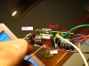
I guess the question is whats the best way to have 2 way communication wirelessly? I bought 2 rx/tx modules (different frequencies)from sparkfun.com and was trying to use them to communicate 2 ways. The attached jpg is one of the 2 boards. The other board is identical except the Rx and Tx frequencies are opposite.

Basically I wanted one board in my car and another outside of it attached to my transmission. I first wanted one board to send a signal which the other would receive and retransmit back to the original one to turn an led on to indicate they were linked. I just tried to get this to work on a bread board and it worked for a few minutes but was really really slow. It wont do it anymore but Im going to bed and will look at it tommorow. Is there a better way for me to do this? Wireless isnt neccesary for my transmission project but would make it a lot easier to install/remove and of course the cool factor :)

I really need 4 byte communication both ways (or more ) so if you guys have a better Idea, let me know. Im not even sure it would work through the body of the car but I havent gotten that far to test it yet. Thanks for the help :D
 

Attachments

  • rf.jpg
    rf.jpg
    151.5 KB · Views: 259
Picture is indeed worth a thousand words (plus it's in focus), however the part numbers for the modules and a schematic are more useful. As it's your project I'm sure you have these to hand and it will save us from having to poke around the site where you bought them.
 
Kind of hard to suggest anything without more info.

Can you post a schematic, or links to the RF modules?
 
nobody has any ideas?

As always with radio modules, use Manchester coding - with (in your case) four byte packets.

Do you need full duplex connections?, if not you might consider a half-duplux system, where the transmitters are turned ON and OFF under software control. You can buy various transceiver modules which do just that.

Even on different frequencies, it's quite likely that the nearby transmitter affects the receiver next to it.
 
I guess I made a mistake with some of my info. I originally bought this package for testing http://www.rentron.com/remote_control/R8_4BIT.htm

I then ordered the 2 pics seperate and the same kind of rx/tx but of a different frequency from spark fun. I make a CB from the schematic on page 4 of the attached pdf. I can make a scematic later and post that as well.

Im starting to think that Nigel is right. I read somewhere about how distances and layouts affect rx/tx performance. I will have to play a little more and get back with with you guys. Also, The recommended antenna length is 30-35cm....does that apply to every frequency? I thought the length depended on the frequency. Also...in the pic you can see I simply soldered in jumper wires to make testing and switching easy on a breadboard. I was told I could drive the input of one PIC with the output of another directly..is that true? THANKS AGAIN FOR THE HELP!
 

Attachments

  • R-8Px.pdf
    562.5 KB · Views: 254
As always with radio modules, use Manchester coding - with (in your case) four byte packets.

Do you need full duplex connections?, if not you might consider a half-duplux system, where the transmitters are turned ON and OFF under software control. You can buy various transceiver modules which do just that.

Even on different frequencies, it's quite likely that the nearby transmitter affects the receiver next to it.

Im totally new to wireless so im afraid I dont know what you mean by full/half-duplex. I basically want an led to indicate there is a connection on the unit in the car. I then need to be able to (using one switch) switch a relay on the remote unit under the car. Finally I need the unit under the car to transmit 2 signals into the car so I can desplay information on an 16f88 driven lcd. Any other method of doing this wirelessly and reliably is acceptable. Im just trying to avoid running wires all over if possible. The project works perfectly with wires already so now Im just trying to cut the "cords" and try something new.
 
Half-duplex means only ONE transmitter is ever operating at one time, so you get no swamping of the receiver by the nearby transmitter.

So transmitter one sends a signal to receiver 2, asking it for the data - then transmitter one turns OFF. Transmitter two then turns ON, and sends the requested data, then transmitter two turns off.

It's like a CB radio, you need to press to talk, and only one person can talk at once.

Ah ha...now I understand. However, I dont think that would work exactly as I wanted. It might come down to that if that is in fact the problem. Thanks for the great info Nigel
 
I am surprised no one pointed out the fact that the RF will be blocked by the car's metal body...unless of course your car made of all plastic.

Dan
 
I am surprised no one pointed out the fact that the RF will be blocked by the car's metal body...unless of course your car made of all plastic.

Dan

Don't tell my car alarm or cell phone that ;)

My alarm sits on the floor of my car.
 
Don't tell my car alarm or cell phone that ;)

My alarm sits on the floor of my car.
LOL but where are the antennas? your cell phone has glass not metal between the antennas and your car alarm most in all probability transmits, if it does, through a remote antenna and in any case also has glass there...

in neither case are talking about extremely low power transceivers with metal between them... try putting your cell on one side of a steel door and your bluetooth headset on the other...

Or try placing your phone on a cookie sheet perhaps and push dial. with the antenna against metal it will either help or more likely destroy your connection. There is a reason that they sell passive cell antennas to stick on the outside of your car windows. Even in the manuals they warn you not to put your hand over the area that the antenna is in lest you impair your phone.

Dan
 
Last edited:
If you make the RX and TX frequencies far enough apart, then they shouldn't interfere with one another. You need a tuned circuit to separate the RX and TX paths; this circuit is called a duplexer. Your cordless phone is full duplex and uses the same antenna to transmit and receive simultaneously. Half duplex though, as Nigel suggests, is easier to implement.
 
Last edited:
If you make the RX and TX frequencies far enough apart, then they shouldn't interfere with one another. You need a tuned circuit to separate the RX and TX paths; this circuit is called a duplexer.

But you need VERY high quality electronics to do that, not the crude designs used for licence free modules - amateur repeaters use complicated devices to transmit and receive only 600KHz apart on the same aerial. If I remember correctly, it's some kind of circular resonator?.

We used to have a commercial mobile radio system at work, the base station transmitted on 86.0625MHz and the mobiles on 76.0625MHz, a 10MHz shift - this allowed you to talk from van to van if you selected the 'talk through' switch on the main station controls. Even with a 10MHz shift, and separate aerials, this reduced performance considerably - it's all long scrapped now though, and we use mobile phones.

Incidently, under 'skip' conditions we used to pickup New York and French taxi services! :D
 
To try and add some clarity to this thread:

The receivers used in these modules are very simple and will almost certainly be overloaded by a transmitter in close proximity, such as on the same PC board.
The transmitter and receiver at each end of your link will need separate antennas.
If you use one antenna to transmit and receive at the same time, these modules will not work, even with the wide frequency spacing you are using (433 and 315 Mhz).
(Yes it is possible to transmit and receive simultaneously on the same antenna, but that technology is orders of magnitude more complex and expensive than these modules.)

As already suggested, use a half duplex arrangement, turn the transmitter off when you are trying to receive.
A PIC with a bit of program should sort it out OK.

The full duplex scheme you are trying to use is doomed from the start.

The metal of the car body will not block the signal, it will certainly have some effect, but the window openings are more than big enough to allow plenty of UHF signal in/out.

The antenna length of 30-35cm will be fine for these simple modules.
Yes the idea antenna length does vary with frequency, but for this application with these modules, dont worry about it.

JimB
 
I really appreciate all the info guys. I have not yet been able to play around with these boards since I first posted but it seems that there is more than enough to suggest that wires are the best/cheapest/most accurate way to get my data from point A to B. Thanks again!
 
The metal of the car body will not block the signal, it will certainly have some effect, but the window openings are more than big enough to allow plenty of UHF signal in/out.

The antenna length of 30-35cm will be fine for these simple modules.
Yes the idea antenna length does vary with frequency, but for this application with these modules, dont worry about it.

JimB
While that would be true for most cases you are talking about very low power systems that you would be extremely lucky to get a multiple reflection path to occasionally make it from roughly dead center of the body off the pavement, off something to one of the sides and back through the window!

UHF is quite directional and with grounded metal in between there is quite a good RF barrier to line of site transmissions. There is a very good reason you lose signal when you go into a steel frame building you know!
 
But you need VERY high quality electronics to do that, not the crude designs used for licence free modules - amateur repeaters use complicated devices to transmit and receive only 600KHz apart on the same aerial. If I remember correctly, it's some kind of circular resonator?.
In RADAR the circular resonator is used this way. At UHF and lower, the isolator (3 port circulator with one port terminated with a dummy) is used to prevent reflected RF, and RF from other transmitters, from getting into the output of a transmitter and causing IMD etc. Tuned cavities are used to separate the Rx and Tx paths by passing and notching the Rx and Tx frequencies. Some sites will have many transmitters and receivers on one antenna.
But you need VERY high quality electronics to do that, not the crude designs used for licence free modules
I should have looked closer at the OP. :eek: I don't think there is much of a tuned RF front end on those modules if any. :rolleyes:
 
Status
Not open for further replies.

Latest threads

New Articles From Microcontroller Tips

Back
Top