Continue to Site

Welcome to our site!

Electro Tech is an online community (with over 170,000 members) who enjoy talking about and building electronic circuits, projects and gadgets. To participate you need to register. Registration is free. Click here to register now.

  • Welcome to our site! Electro Tech is an online community (with over 170,000 members) who enjoy talking about and building electronic circuits, projects and gadgets. To participate you need to register. Registration is free. Click here to register now.

Trying to create a lighting effect for an NES control pad

Status
Not open for further replies.

SasquatchWing

New Member
Greetings. I'm trying to create a new costume for an upcoming convention and am looking to spice things up with a electrical device or two.

The character I'm going as is Captain N, the Game Master. The name might sound familiar to those who have seen the Saturday morning cartoon of the same name in 1989-1991. Anyway, I'm trying to create a control pad (worn on the belt, of course), that has an 8-light display on top. Those familiar with the aforementioned show will know that whenever Kevin (Captain N) used one of the control pad's powers (to jump, pause nearly everything around him, etc.), he gradually depletes power, as shown by the lights that turn off one by one.

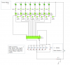
What I want to try to do is to make a device that emulates that aspect. The eight green lights would light up as so:

[*][*][*][*][*][*][*][*]

Whenever I press a button on the control pad (up, down, left, right, A, B, or start), a light would turn off, like so:

[*][*][*][*][*][*][*][ ]

With each button press, this "power meter" would deplete until it finally runs out, as illustrated here:

[*][*][*][*][*][*][ ][ ]

and here:

[*][*][*][*][*][ ][ ][ ]

and here:

[*][*][*][*][ ][ ][ ][ ]

and here:

[*][*][*][ ][ ][ ][ ][ ]

and here:

[*][*][ ][ ][ ][ ][ ][ ]

and here:

[*][ ][ ][ ][ ][ ][ ][ ]

and here:
[ ][ ][ ][ ][ ][ ][ ][ ]

Of course, I'd like my power back sometime, so why not add a power-up, such as the select button I didn't mention.

[*][*][*][*][*][*][*][*]

BING! And the whole process starts all over again.

I will admit that I am a bit of a novice at this whole thing, and am trying several solutions via Yenka (a design program I found on the web), but when I test out the 'solutions', I keep blowing up one IC or another.

Any help would be appreciated, and thanks in advance.
 
Last edited:
Is the power meter and the eight lights the same thing or 2 different sets of lights. Can't tell from the pictures on line.
 
I've been referring to the series of eight lights in question as the "power meter". Sorry for the confusion.

Also, I have a few beginner's questions:

- Apparently, I just need to properly ground the circuit to an 'earth ground'. In this sort of application, what would be a good grounding point?

- I'm looking over various integrated chips, such as the 4014, 4015, 4017, etc. What kind(s) of IC(s) would be best suited to this application?

- Since I will most likely be using ICs, there should be very little power going to them, so I'm starting off with a 6v battery. Beyond the ICs used to select the state of the lights, that leaves little power to the lights themselves. Is there any way to increase the power to the lights without overloading the ICs?
 
Last edited:
Alright! I think I have a working preliminary design, so please let me know if there's anything I might be missing. And yes, this is taken from Yenka and I know that program -pretends- that it has it's own power source and ground for the ICs (4017, 4050 (2), and 4071 (2)). I do plan on adding direct power and ground to all ICs.
 

Attachments

  • Captain N project schematic.PNG
    Captain N project schematic.PNG
    41.3 KB · Views: 373
Last edited:
I've tried a breadboard prototype of the circuit, and I've run into a couple of issues. I've made up a somewhat better design to post in this attachment. I think I am missing a few things, including a 'de-bouncer' for the button-pressing. I have a few questions on this.

1. When I tried out the circuit, the lights would light up, and the reset on the 4017 decade counter would even work as it's supposed to, but when I send pulses to the clock itself, I would manage to get one in before it would stop accepting pulses. Is this caused by the lack of a de-bouncer?

2. As illustrated in the latest schematic, I plan on using several buttons (Up, down, left, right, A, B, and start) for one function, in that whenever any of those buttons are pressed, it would advanced the circuit. In addition, I would make one button (the select button) a reset button. When putting in a de-bouncer, do I need to make one for each button, or can I get away with using one de-bouncer on several buttons connect to the same line?

3. In general, are there any ways to improve this design? Any comments would be a great help.

Thanks!
 

Attachments

  • Captain N controller Belt 2.jpg
    Captain N controller Belt 2.jpg
    278.7 KB · Views: 225
I haven't even gotten the microcontroller stuff yet, but WOW! If I knew using something like PICAXE would be so easy, I would've gone right to this to begin with... *facepalms*

Ah, well. No use crying over spilled milk.

Take a look at this little flowchart and please tell me if I'm making any errors. What I hope to do is prevent the sequence from cycling whenever I hold down one of the buttons, hence the loop within the first input test. I did take a few liberties with the picture that Yenka seems to like to forget, such as the power and ground leads for the circuit, and I've made notes on the flowchart that wouldn't fit in the nice little space.

Also, what stuff should I purchase to make this happen? The flowchart assumes a PICAXE 20M IC, but I get the feeling I could get away with using an 18X IC. Again, please let me know if I'm mistaken in my assumptions.

EDIT: I've decided to get a starter kit for an 18M2 chip, which should be arriving in a few days. In the meantime, I've set up another schematic with proper notations (Not a Yenka one, thank goodness). My apologies if it's not quite as readable. I'm still trying to get the hang of creating custom ICs using ExpressSCH, and ExpressPCB for that matter.

One question does come to mind: If I'm not mistaken, it should be possible to transfer the chip to a PCB that doesn't have a PICAXE download circuit so long as I ground the Serial In (pin 3) and add the 10kΩ/22kΩ resistors. Am I doing this right, or is there something I need to change?
 

Attachments

  • Captain N microcontroller flowchart.JPG
    Captain N microcontroller flowchart.JPG
    119.2 KB · Views: 431
  • Captain N controller Belt PICAXE.JPG
    Captain N controller Belt PICAXE.JPG
    150.4 KB · Views: 278
Last edited:
Status
Not open for further replies.

New Articles From Microcontroller Tips

Back
Top