Continue to Site

Welcome to our site!

Electro Tech is an online community (with over 170,000 members) who enjoy talking about and building electronic circuits, projects and gadgets. To participate you need to register. Registration is free. Click here to register now.

  • Welcome to our site! Electro Tech is an online community (with over 170,000 members) who enjoy talking about and building electronic circuits, projects and gadgets. To participate you need to register. Registration is free. Click here to register now.

True 0-5v Power Supply

Status
Not open for further replies.

billyjojimbob

New Member
Hi Guys

I need a PSU that goes from 0-5v.

It needs to go down to 0v, well, 0.5v I could get away with as the equipment I need to test needs 0.6v for the first test to kick in.

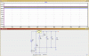
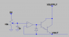
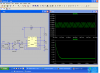
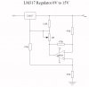
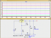
I've been trying the attached circuit but can't get it to go below just over 3v.

Any ideas?


Cheers
 

Attachments

  • 0-5v cct.jpg
    0-5v cct.jpg
    61.5 KB · Views: 355
hi,
Whats the Vsupply to the LM317.? also what current levels are you wanting,?
 
Hi Eric

Supply is 9v and current is about 100mA.

hi,
As I guess you know, about 1.25V is about the lowest you can output from a LM317.

What I have seen are supplies which have a low voltage zener or 2 or 3 diodes in series at the 0V input end of the supply.
These give about 1.4V thru 2.1V drop along the 0V line, the ADJ of the LM317 is connected to input side of the diodes/zener, so the output of the supply is ~0V thru +V.

I will try to find the circuit.
 
hi,
This is a simple way to get close to 0V output.
The regulation is not as good as a direct connection LM317, bit does enable a close to 0V out.
Choose a 1Watt zener also the 220R fixed resistor is required.
 

Attachments

  • AAesp01.gif
    AAesp01.gif
    24.9 KB · Views: 312
Look at the LT3083. It is a little harder to use than the LM317 but can be set to very low voltages!
Input voltage must be less than 23V.
Current 3A. I think there is a 1A version.
Current must be greater than 1mA!
Low dropout 0.3V.
Use only one resistor to set voltage. Can be set to o volts.
See fig. 8 in data sheet.
 
hi,
There are a number of variations.
The 'best' way is to use two supplies +/-V
 

Attachments

  • AAesp02.gif
    AAesp02.gif
    31.1 KB · Views: 257
The zener in the return current path will give poor load regulation. The circuit in the app note uses an extra rail (negative rail) & allows the zener reference to pass a steady current & therefore has better load regulation.

Another way of achieving the 0-5V output is using the attached circuit. The opamp inputs and output must be able to operate close to 0V. A 5V regulator can supply the 5V reference.
 

Attachments

  • REGULATOR.png
    REGULATOR.png
    6 KB · Views: 269
The LM317 datasheet shows a way to use a second LM317 in the negative rail to act like a fixed 1.25v zener, to give full adjustment down to zero volts.

Personally I like the opamp approach.
 
Negitive Supply

Here is a cheap & dirty negitive bias supply.
 

Attachments

  • - sup.PNG
    - sup.PNG
    73.5 KB · Views: 233
Last edited:
The LM317 datasheet shows a way to use a second LM317 in the negative rail to act like a fixed 1.25v zener, to give full adjustment down to zero volts.

Personally I like the opamp approach.

hi Roman,
Personally I would go for a second battery in the OP's set up. IIUC he is using a 9V battery.??

If he is not using a battery then a 9Vdc 'wall wart' would give the required offset voltage.

As always we dont know the application, does the OP want the set up for a 'one off' test or does he want to make a 'decent' '0V thru +5V' regulated 1Amp power supply.???
 
It's a piece of portable test equip. Powered by a PP3 9v battery. It's just for occasional use and will just sit in my tool cupboard most of the time.

I built the original cct using the diagram at the begining of the post, but couldn't get the o/p below about 3v.

Any ideas of what is wrong with it?

Hi,
With a single voltage source the LM317 can be configured to give an output voltage of ~1.25/1.5V

Try some of the ideas suggested in order to get 0V

EDIT:
NOTE: in your original circuit the 741 is powered by positive and negative voltage, thats how the 0V out is possible.
 
Last edited:
Powered by a PP3 9v battery....I built the original cct using the diagram at the begining of the post, but couldn't get the o/p below about 3v.
It needs a negative supply for the opamp. Otherwise the output voltage is going to be the 1.25V of the LM317 added to the minimum output voltage of the opamp (which I guess is 1.75V in your case).

If you want to use a single 9V battery, you can use e.g. one of the circuits posted. There's not much headroom if you're using an LM317 & 9V supply: The LM317 needs ~1.7V across it and you need a negative supply 1.25V below the 0V reference which means 8V minimum for 0-5V output, so if the battery's a little flat or the opamps are not ideal, it won't work.
 
Last edited:
Status
Not open for further replies.

Latest threads

New Articles From Microcontroller Tips

Back
Top