Continue to Site

Welcome to our site!

Electro Tech is an online community (with over 170,000 members) who enjoy talking about and building electronic circuits, projects and gadgets. To participate you need to register. Registration is free. Click here to register now.

  • Welcome to our site! Electro Tech is an online community (with over 170,000 members) who enjoy talking about and building electronic circuits, projects and gadgets. To participate you need to register. Registration is free. Click here to register now.

Trouble with seven segment display.

Status
Not open for further replies.

Jeggyman

New Member
Hi all, I'm new to electronics and recently purchased myself some basic equipment in order to begin experimenting with it because I want to make a hobby out of it. One of the things I bought was a seven segment display from radio shack. Part number 276-075. I tried to hook it up according to the information on the back but was unsuccesful. I thought perhaps I could post the information they give on the package and tell you guys how I interpreted it and then you could tell me where I've gone and how I could correctly wire it.

First off there are 10 pins on the display. They are marked as follows on the back of the package. (the package lists 4 non-existent pins as no pin).
1. Anode F
2. Anode G
3. No pin
4. Common Cathode
5. No pin
6. Anode E
7. Anode D
8. Anode C
9. Anode RHDP
10. No pin
11. No pin
12. Common Cathode
13. Anode B
14 Anode A

It also lists some maximum ratings as follows.
Forward current: 30mA
Forward Voltage: 2V
Reverses Voltage: 5V
Power dissipation: 100mW

Here's how I interpreted this information. I decided that the common cathodes must hook up to the positive voltage of the batery permanently. I assumed the way the display would work is the cathode pins would be permanently connected to the positive voltage and then segments on the display would light up corresponding to which of the Anodes A through F were connected to ground. I wasn't sure what Anode RHDP on pin 9 meant so I thought that it might be a pin that has to permanently connect to the ground. So the set up I had was pin 4 and 12 connected to + voltage and pin 9 connected to ground. Then I tried connected the various other pins to ground in order to make them light their particular segment of the display. This however was unsucesfull. Can anyone tell me the correct way to to wire one of these things. If you could also explain the significance of the section that contain forward and reverse voltages and current I would appreciate it. I know that they dictate the maximum amount of current and voltage the part can handle but I'm confused as to what the forward and reverse mean. Thanks in advance.
 
You have te polarity backward, Jeggyman! The common cathode connection must be grounded while the anode connections are connected to a positive source. These are LEDs, so be sure that you have a series current-limiting resistor on each of the anode connections or you new display will go up in smoke. A common cathode display has all (or most of the) cathodes connected together internally. "RHDP" = "right hand decimal point". On your display, both of those common cathode pins (pins 4 and 12) are likely connected together internally, so only one need be used. That internal connection is handy for creating an "automatic jumper" on a circuit board you may design.

Common anode displays are a little more common and a typical application may have a 7447 decoder/driver chip driving a common anode display.

Dean
 
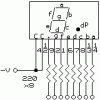
Here's a quick diagram on how you could hook up this display. If you use 5 volts for a power source, use eight 220 ohm resistors, this will give you 14mA or so thru each segment. Don't use a resistor smaller than 120 ohms, or you could damage the display. To determine the segment current use this formula: (Vs-Vf)/R, where Vs=source voltage, Vf=led forward voltage, R=resistor value ... (5-2)/220=0.0136A (13.6mA). The maximum current for a segment is listed as 30mA. Connect the negative power to pin 4, 12 or both. Connect the positive power to any of the resistor pins to make that particular display segment light. JB
 

Attachments

  • cc_led.gif
    cc_led.gif
    2.2 KB · Views: 981
Thanks for all the help guys, I'll try out this setup as soon as I get home. Just so I know, for future reference cathodes always connect to negative voltage and anodes always connect to positive voltage? Also could explain what is meant by forward and reverse voltage? Thanks.
 
I think I can take a stab at the forward / reverse voltage.

Forward voltage simply stated, is the voltage that is necessary for the PN junction of the LED to conduct. Thus, if you were to apply 1 volt to the circuit, the PN junctions of the LED's would not conduct, thus, the LED's wouldn't light up. Of course, this is when forward bias is used (Eg, anode to positive, cathode negative)

Reverse Voltage, what I think they are speaking of here is the amount of voltage that is necessary to allow minority carriers (intentional "imperfections" in the P and N junctions) to conduct. Thus allowing leakage current.

It could also mean the reverse break down voltage, meaning that if voltage is applied oppositely, the PN junction would break down and cause current to flow in the opposite direction of the bias (reverse bias).

Maybe someone can clarify if needed.
 
umm...

Yeah, maybe someone could post to clarify that a little? I'm sorry but I'm not very experienced with electrical equipment and that was a little over my head. Maybe someone could explain what the PN junction is? Thanks.
 
To understand the PN Junction, one must first understand the constuction of a semiconductor diode. Simply put, a basic silicon diode is constructed of two sections of silicon that have been "doped" differently so as to cause them to have somewhat opposite electrical characteristics.

The doped silicon is known as N-type and P-type, with the N-type being used for the cathode (K) side of the diode, and the P-type being used for the anode (A) side of the diode. The N-type silicon has an artificially produced excess of (free) electrons, while the P-type has a small number of "holes" where electrons have been removed in the doping process. It is this abundance of free electrons in one region and the available spots for electrons to settle in the opposite region that give a semiconductor diode its unique abilities.

Somewhere in the middle of of the diode, where these two sections meet, is the region known -- for now obvious reasons -- as the PN Junction.
 
OK -- in re-reading my last response, maybe I didn't go far enough...

Forward Voltage is the amount by which the anode potential exceeds the cathode potential, measured in volts.

Forward Current is the current in amperes that is present at a specified forward voltage, flowing from anode to cathode.

Reverse Voltage is the amount by which the cathode potential exceeds the anode potential, measured in volts.

Reverse Current is the current in amperes that is present at a specified reverse voltage, flowing from cathode to anode.

Bias refers to the voltage applied to a diode, which is either forward or reverse, depending upon its polarity.

Forward Bias is such that it will allow the diode to conduct current, i.e. the anode is more positive than the cathode.

Reverse Bias is such that it will cause the diode to block current, i.e. the cathode is more positive than the anode.

Reverse Breakdown Voltage is the maximum reverse voltage that a diode can experience without causing failure of the diode, e.g. allowing excessive reverse current.

Reverse Recovery Time is the time that it takes for a diode to switch from its "conducting" mode to its "blocking" mode when the polarity of the applied voltage is reversed.

Now... it's important to understand that when discussing voltage and current with respect to semiconductor diodes, it is customary to speak in terms of "the conventional theory of flow" rather than in terms of "the electron theory of flow".

It is known and understood that current is simply the movement of electrons, and that electrons flow from an area of abundance to an area of depletion (i.e. from negative to positive) -- like charges repel, remember? However, in the earliest days of the study of electricity, it was thought that the opposite was true -- that electricity flowed from positive to negative. This early concept is called the "conventional theory", and it is commonly used when discussing semiconductors as it somewhat simplifies the understanding of them.

If a more negative potential is applied to the anode than is present at the cathode, a diode is said to be "reverse biased" and it will block current, except for a minimal amount of "leakage" which is present in most diodes. If the reverse bias is continually increased, at some point the reverse breakdown voltage will be reached, at which point the diode will no longer be able to block reverse current.

If you want or need more info on this, post back and I'm we can help you further... :)
 
Thanks

That actually helps out a lot. I think I get it now. Thanks a lot for the help, you guys are great :).
 
Status
Not open for further replies.

Latest threads

Back
Top