Continue to Site

Welcome to our site!

Electro Tech is an online community (with over 170,000 members) who enjoy talking about and building electronic circuits, projects and gadgets. To participate you need to register. Registration is free. Click here to register now.

  • Welcome to our site! Electro Tech is an online community (with over 170,000 members) who enjoy talking about and building electronic circuits, projects and gadgets. To participate you need to register. Registration is free. Click here to register now.

Trouble with op-amp around 0V

Status
Not open for further replies.

EtecDude

New Member
Hello everyone,
My requirements are simple: 24V (single-ended) supply, 8 V/V gain. I'm not sure why this is being such a pain.

I need a 0-20V output. I have a DAC that provides 0-2.5V so I need a simple x8 gain stage to bring this to 0-20V. My supply is a fixed 24V. The attached schematic shows that I'm trying to use a simple non-inverting design. The op-amp is an L272A - this was chosen for its high supply voltage capabilities.

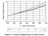
The circuit works great, and is linear from around 0.3 to 20V. But when I get down to around 0.3V or so, the output won't go to zero, it levels off at about 0.2V. The DAC output is correct, and linear all the way to zero.

Can someone help me understand why this is happening? I've done a lot of research and feel that it may have to do with Vos, the input offset voltage of the op amp. Is it my design or op-amp selection?

Thanks,
Jake
 

Attachments

  • dac_amp.png
    dac_amp.png
    9 KB · Views: 164
hi,
The way I read the data sheet is that the swing to zero with a single supply is based on a load current of approx 0.1A.
 
Last edited:
Thanks for the quick reply, and correction :)
Did you get this from Figure 3-2 (assuming the Fairchild datasheet)?
 
Last edited:
Thanks for the quick reply, and correction :)
Did you get this from Figure 3-2 (assuming the Fairchild datasheet)?

hi Jake,
Yes its the Fairchild d/s.

What load is the OPA driving.? are you measuring the OPA output when it its loaded or unloaded.?
 
Loaded. I believe this was with a 1k load (I can confirm the value tomorrow) which at 0.3 V would give 0.3mA draw. This should ideally drive any range of loads but high impedance loads will be necessary...
 
Loaded. I believe this was with a 1k load (I can confirm the value tomorrow) which at 0.3 V would give 0.3mA draw. This should ideally drive any range of loads but high impedance loads will be necessary...

hi,
You could add some offset to the input of the OPA if that would help.
I expect you have tried disconnecting from the DAC and connecting that input resistor to 0V and then check the Vout.???
 
hi,
You could add some offset to the input of the OPA if that would help.
I expect you have tried disconnecting from the DAC and connecting that input resistor to 0V and then check the Vout.???

Yes. I even re-built just the op-amp stage, in a standard inverting configuration, and fed it with a +/- 22V power supply. Rf=82k and Rin=10.25k (Gain=8). I connected it to GND, and the Vout is around 80mV. I then multiplied the resistors by ten, Rf=820k and Rin=102.5k. This improved, but Vout was still around 70mV. I really need this to go to zero (max 10mV).
 
+36V not high enough ???

Ah, I read the datasheet wrong, I think.

"DC Supply Voltage (Between V+ and V- Terminals) . . . . . . . . . 36V"
This is sufficient for the 0-24V supply.

Can you help explain to me the "Max Output Voltage (Note 4) (See Figures 2, 8)" page 4, the 5th row of the table? [LATEX]V_{OM+}[/LATEX] and [LATEX]V_{OM-}[/LATEX]

Also, the maximum output current is only 10mA - but can I supplement this with a pass-transistor?
 
Last edited:
I didn't realise you required an accurate linear 0 to 20v output, that could either source or sink more than 10mA!
I'll have to leave advice on that to our more experienced 'power output' gurus! Adding 'pass transistors' and maintaining the kind of linearity, over a larger current range, is a bit beyond my design capability. Sorry about that!

If your supply voltage is all +ve relative to ground, then the VOM+ and VOM- values are probably not appropriate. We are talking here about a voltage swing which is all +ve, with respect to ground.
 
I had a similiar problem with a instrumentation OpAmp a while back, INA128. It was noticed that the common mode votage range was from V- +1.7 to V+ -1.4, meaning that I had to be 1.7V above the low rail and 1.4V below the top rail. Unfortunately, I don't see that listed on the datasheet for the L272A or anything similiar. So it may not apply, but you describe the exact same issue I had. I ended up reducing the lower rail voltage. My system ended up powered -5 and +12V and worked perfectly.

You'll have to forgive me, it's been a while since I worked with these, so I may be off base or wrong.
 
You are not reading the data sheet. This is the plot from the data sheet of how low the output will pull if Vee is tied to -12V, and it clearly shows that the output will not pull any closer than 250mV, even if the load current is 100ma. It you tie Vee to 0V, the output will be at +0.25V. The input common-mode range is not specified, and that may problematic, too.

For a single supply operation, you should be looking for an opamp which is billed as being rail-to-rail IN and OUT. This one is not.
 

Attachments

  • L272Aswing.png
    L272Aswing.png
    25.5 KB · Views: 147
Last edited:
Also, the maximum output current is only 10mA - but can I supplement this with a pass-transistor?
I didn't see where you specified the drive requirements, only 24V supply, 0-20V out, gain of 8. I may have missed it; what is the drive requirement?

Depending on the above & on the allowable current consumption, you can convert the opamp to work in a kind of Class-A configuration by putting a load resistor on the output to ground. This will reduce the lowest output voltage. It must also be helpful to put 2 contra-polarity parallel diodes in line with the output of the opamp (in addition to the pull down resistor) to offset the output voltage further (and add some nice cross-over distortion - might matter depending on the signal you're sending & on the load; then again it might not be an issue (or present) for your application at all).
 
Hello there,


Some op amps will not go all the way to ground when the negative supply voltage is also at ground (0v). There are at least two reasons for this.

One is the input offset voltage, which when multiplied by the circuit gain, may cause the output to be much higher than ground for 0v input.
The second reason (and the one i'll address here) is that the output stage is not designed well enough to reach down to 0v (sometimes the sat voltage causes this).

If the output voltage is caused by the first reason above then you have to supply some input offset adjustment to compensate, which im sure you know.

If the output voltage is caused by the second reason above however then all that has to be done is to drop some voltage so the output goes all the way to 0v.
One simple way to get this to happen is to insert an Si diode in series with the output, with the anode (not the cathode) connected directly to the output of the op amp, and the feedback resistor coming off of the cathode instead of the op amp output, and the load taken from the cathode of the diode. What this fix does is it forces the output of the op amp to be higher than ground (roughly 0.7v) in order to produce a cathode voltage of exactly zero volts. That provides the load circuit with a true zero volts as long as the load does not source too much current.
The other requirement is that another load resistor might have to be added from the cathode to ground in order to properly pull the load down to 0v. This resistor value will have to be chosen properly in order to both get the load down to 0v and also to allow the op amp to still be able to source the required max output voltage, keeping in mind that there is now 0.7v less than before. If there is no resistor that can satisfy both these conditions, then it might be necessary to add an active output stage rather than a simple diode, or another possible solution.
The other possibility is to provide a small negative bias to the negative supply rail of the op amp. This can be done sometimes if the grounds of input and output can be taken from a different ground other than true ground. the other ground is produced by using a diode in series with the negative lead of the power supply where the "true" ground becomes the anode of the diode while the cathode becomes the op amp minus supply and power supply ground. This puts the op amp minus supply rail at roughly -0.7v compared to the analog grounds. This is often just enough to get the output of the op amp to go to a true zero volts. Of course a cap across the diode is a good idea too.

It would help if we knew what kind of load you were trying to drive with the op amp.
 
Last edited:
Status
Not open for further replies.

New Articles From Microcontroller Tips

Back
Top