axeman2ooo
New Member
hi
built the circuit for the Micromitter, but I think something is not right...
The instructions say:
"
(1). Set the transmission frequency using the DIP switches, as shown in Table 1. Note that you need to select a frequency that is not used as a commercial station in your area, otherwise interference will be a problem.
This is done, no problems
(2). Connect your multimeter's common lead to TP GND and its positive lead of to pin 8 of IC1. Select a DC volts range on the meter, apply power to the Micromitter and check that you get a reading that's close to 5V if you're using a DC plugpack.
This is done, no problems. Using a plugpack selected to 5V
Alternatively, the meter should show the battery voltage if you're using AAA cells.
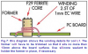
(3). Move the positive multimeter lead to TP1 and adjust the slug in L1 for a reading of about 2V.
"
This is the problem area. reading is 0.6VDC and adjusting the slug makes no change. I have no signal to the FM, but everything seems fine, checked the tracks with the diagram perfectly, making sure with a blade that nothing is touching. measured the diodes, i think they are ok...
any ideas? driving me insane...
built the circuit for the Micromitter, but I think something is not right...
The instructions say:
"
(1). Set the transmission frequency using the DIP switches, as shown in Table 1. Note that you need to select a frequency that is not used as a commercial station in your area, otherwise interference will be a problem.
This is done, no problems
(2). Connect your multimeter's common lead to TP GND and its positive lead of to pin 8 of IC1. Select a DC volts range on the meter, apply power to the Micromitter and check that you get a reading that's close to 5V if you're using a DC plugpack.
This is done, no problems. Using a plugpack selected to 5V
Alternatively, the meter should show the battery voltage if you're using AAA cells.
(3). Move the positive multimeter lead to TP1 and adjust the slug in L1 for a reading of about 2V.
"
This is the problem area. reading is 0.6VDC and adjusting the slug makes no change. I have no signal to the FM, but everything seems fine, checked the tracks with the diagram perfectly, making sure with a blade that nothing is touching. measured the diodes, i think they are ok...
any ideas? driving me insane...