Continue to Site

Welcome to our site!

Electro Tech is an online community (with over 170,000 members) who enjoy talking about and building electronic circuits, projects and gadgets. To participate you need to register. Registration is free. Click here to register now.

  • Welcome to our site! Electro Tech is an online community (with over 170,000 members) who enjoy talking about and building electronic circuits, projects and gadgets. To participate you need to register. Registration is free. Click here to register now.

Triggering Stop Watch

Status
Not open for further replies.

willeng

Member
Hi Everyone,
Having a collection of unfinished projects, I am determined now to have them finished & working.
The projects are unfinished due to my lack of electronics knowledge--full stop!
Could I get some advice on how to go about this particular problem I have with this project.

I made a Stop Watch circuit using an Arduino Mega board, which can be found here:

https://embedded-lab.com/blog/chipkit-project-5-digital-stopwatch-seven-segment-led-display/

I modified the code to suit what I required & it is working fine.

The idea behind the project was to:
Trigger the Stop Watch (ON at a particular set Frequency or Voltage)
then
(Off at a higher set Frequency or Voltage)
So, Stop Watch (On) at say 500Hz or X voltage then (Off) at say 2kHz or X Voltage.

I am not sure how to go about this correctly but this is how I was going to attempt it very basically?

The Stop Watch Circuit at the moment has a Tact Switch to "start & stop" the Stop Watch.
I was going to replace the Tact Switch with a Relay that gets triggered to "start & stop" the Stop Watch at the required Frequencies or Voltages.
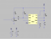
I thought of using a 555 timer as a one shot pulse to trigger the Relay On/Off when required.

I am not sure how to get the required pulses at preset frequencies or voltages to be able to trigger the events?

Any Help would be greatly appreciated.

Cheers
 
It's always bad when you don't get a reply, either you've asked something stupid or?
I realize that it can be done with the Arduino but I don't have the skills to tackle the problem with programming.

There is probably a simpler way to do this but I have pieced together what I think may work, would you be able to have a look at the schematic & see what you think?

Obviously on the Schematic the Low Frequency Circuit Triggers the Stop Watch ON & the High Frequency Circuit Triggers it OFF.


Thanks
Cheers
 

Attachments

  • Stop Watch Trigger Circuit.PNG
    Stop Watch Trigger Circuit.PNG
    71.5 KB · Views: 179
You left a lot of specifications blank.

Frequency range?
Voltage range?
and whether your looking at the time from e.g. 500 Hz to 1000 or from 1000 Hz to 500 Hz or both?

I now understand that the stop watch uses a typical start/stop signal.

A reminder that relays have an actuation time (10-20 ms typical).

At one time, I did a search for Arduino frequency measuring routines. Basically you have to chose either a time base method or a count method and use interrupts. You can look at rising or falling edges. Sometimes you have to clean up the edges with a schmidt trigger.

I'll wait for your answers first.

meanwhile: https://www.lmgtfy.com/?q=frequency+counting+arduino where you can see the frequency range matters a bit.
 
Hi Kiss,
The frequency range I can adjust by means of a toothed wheel & optical pickup to suit so I didn't add that specification, sorry about that?
I was going to adjust this specification to suit whatever the circuit required so to speak.
I will be looking at the time from Low to High - Low Frequency to High Frequency, I was not sure if it was easier to do this by means of Frequency or Voltage?.
Low Frequency setting to trigger the 'Stop Watch On' & the High Frequency setting to turn the "Stop Watch Off".

Yes, I understand about the actuation time of the relays, the Stop Watch resolution is set at 0.1 seconds, I had it at 0.01 seconds but there is no need for that accuracy, 0.1 seconds is very accurate for the requirements I need. I figured if the actuation time of the relay was the same each time that it wouldn't corrupt the readings?

I would rather do this with the Arduino if I could work it out?

Basically each small test piece will accelerate at it's own rate differently under it's own power (with the same load on each test piece each time) so I need to record the time taken from one set rpm or in this case Frequency to another set rpm-Frequency.

Thanks for the reply
Cheers
 
Hi Willeng,

Many years ago when my son, now 30, was a Cub Scout, I helped him on a project to time Pinewood Derby cars accurately. I did basically what you are doing with an inexpensive stopwatch from WalMart. The main difference was that I used a common 2n2222 transistor as the switch (many other transistors will work, as the current is quite small). You may want to consider doing that. I stayed up well past midnight to get it working -- don't forget the base resistors. Its biggest advantage is that you do not have to contend with switch bounce or contacts sticking. The 2n2222 or any substitute will have adequate frequency response for your purpose.

We had no problem timing to 10 ms. After decades of not doing anything in electronics, that was my very first project -- fond memories. Unfortunately, the schematics are about 42 miles from me, and I won't be going there until next Wednesday. Nevertheless, the design is pretty obvious. I suggest you consider it.

Sorry to get a little maudlin with you.

John
 
Hi John,
Not sure I understand how the Stop Watch is triggered automatically On & Off at pre set frequencies with just a Transistor?
Maudlin, I have never heard of that before, had to Google it:).

Thanks for the reply.
Cheers
 
You just use the transistor instead of a relay. When the base of the transistor is high (>0.6V relative to ground) , it turns it on, when low(<.6V relative to ground) , it turns it off. For your stopwatch, the current needed is orders of magnitude less than a relay requires.

Here are some links that may help:
https://en.wikipedia.org/wiki/Resistor–transistor_logic
https://learn.sparkfun.com/tutorials/transistors/applications-i-switches

Glad you had to go to the dictionary/Google. Good practice.

John
 
Hi John,
Ahh yes of course, I totally misread your post. You had me scratching my head there for a moment:)
Yes, that is a much better method than a relay, thanks for that, much appreciated.

Thanks John
Cheers
 
I would do it as John suggest replacing the tactile switch with a transistor. Now your transistor is the switch and using a transistor as a switch is pretty common.

Now you mention looking at a voltage or a frequency. You have a few options here depending on how specific you want to get. For example if I want to look at a voltage I could use a **broken link removed** or even a Window Comparator circuit. Frequency? I could use a F/V (Frequency to Voltage) converter and run that to a comparator. There are other ways to do this all dependent on your specifics.

Ron
 
The stopwatch is not a bad idea. I've used these http://www.excelitas.com/downloads/DTS_vtl5c1c2.pdf which are basically similar to optoFETs, but with leads, so they don't require much in terms of modifications. You just have to check what minimum resistor will operate the stop watch switch.

You could use your frequency to voltage converter and a comparator and voltage reference. Measuring and setting the voltage might be adequate for you.

So, yep, you do have to get it in sync. ut you do have:
a) greater than low frequency - pulse (one shot)
b) greater than high frequency pulse (one shot)

Linear technology has introduced these http://cds.linear.com/docs/en/lt-journal/LTJournal-V20N4-01-df-Timerblox-Andy_Crofts.pdf timers, but you probably have 555's hanging around.

Typically, you might get a voltage reference across say a 10K 10T pot and buffer the wiper with a low offset OP amp.
the turns-counting dial may be enough resolution for you.

If they are fixed points, then 10T trimmers might work fine. The important thing is to BUFFER the reference.
 
Thanks Reloadron & Kiss,

Ok you both mention the Frequency to Voltage method which is good as I have some LM2917N Ic's.
I have some LM311P comparator Ic's as well.
Also 555 Ic's

Just so I understand this correctly, I have the frequency into the LM2917 which obviously converts the frequency to voltage.
I set a reference voltage on the LM311 & when the input voltage to the LM311 is the same as the set reference voltage the comparator switches On triggering a one shot circuit that triggers the Stop Watch On.

So I need a second LM311 circuit for the higher reference voltage which triggers the Stop Watch Off--Yes?

Does the LM311 comparator circuit for the Low frequency trigger remain in the ON state after it has been triggered?

I have to read more about this but haven't had time yet.

Thanks
Cheers
 
Last edited:
Thanks Reloadron & Kiss,


So I need a second LM311 circuit for the higher reference voltage which triggers the Stop Watch Off--Yes?

Does the LM311 comparator circuit for the Low frequency trigger remain in the ON state after it has been triggered?

Cheers

Yes to both questions. You want an edge triggered monostable. This https://www.jameco.com/Jameco/Products/ProdDS/13611FSC.pdf does nicely because they can be used to detect both a positive or a negative edge. The max timing interval is restricted. There is another in the family that may have a longer interval.

How you get your reference though can be different. Many times you can buy and OP amp, comparitor and or reference together.

The LM10 https://www.ti.com/lit/ds/symlink/lm10.pdf has been around for years So has the LM311.

You end up with a lot of tradeoffs because of supply issues. e.g. You generally need something larger than 5V to get a 5V reference. If you use a single supply OP amp, you have issues with the low end. The reference may have low output capability and an OP amp adds offset. For the comparitor to work, the OP amp must be driven from a low Z source.

So, lots of options.

So, in one scenario, I could envision say a 5V reference then buffered. To that buffered output, drive two 10K pots. Then buffer the wiper to apply to the comparitor. It's not a good idea to use the power supply.

You see a lot of 1/2 Vcc as an artificial zero. This is done a lot in automotive sensors. They also make the reference "ratio-metric", so they don't need a precision reference.
 
Thanks Kiss,

Obviously the CD4528 is best as you suggest but until I can get some can I just use a 556 connected as shown in the attachment-(555 shown) just to test things out?

I get what your saying about buffering the reference voltage.

The LM339 is ok to use?

Thanks for the help, sounds good!

Cheers
 

Attachments

  • 555 One Shot.PNG
    555 One Shot.PNG
    22.2 KB · Views: 164
Thanks Kiss,

Obviously the CD4528 is best as you suggest but until I can get some can I just use a 556 connected as shown in the attachment-(555 shown) just to test things out?

It's probably not a good choice because of the output time period. There is a 4098, 4028 and then this one; http://www.onsemi.com/pub_link/Collateral/MC14538B-D.PDF which would go to 10 s. The latter is equlivent to the CD4538. http://www.google.com/url?sa=t&rct=j&q=&esrc=s&source=web&cd=1&cad=rja&uact=8&ved=0ahUKEwjYzZT_hJzKAhXHSyYKHXOEAvEQFgggMAA&url=http://www.fairchildsemi.com/datasheets/CD/CD4538BC.pdf&usg=AFQjCNFbs1iE4ZwBIUTKeZMZTL7atwoDUA&sig2=r6CDN3JRwLD0HA1MqaIpdQ

There's a few minor differences. One is geared for precision.

Then, of course, there is this one (LTC6993-x): http://cds.linear.com/docs/en/datasheet/69931234fc.pdf but the power supply is limited to 5V.

Pick your poison.

I get what your saying about buffering the reference voltage.

Good! Off on the right foot.

The LM339 is ok to use?

Sounds good.

Thanks for the help, sounds good!

As long as you do all the work!
 
I found the schematic I used on this PC. Here is is. The diode was necessary as we were using a higher voltage than the stopwatch supply. The "stopwatch switch" represents the two existing contacts in the stopwatch.

John
 

Attachments

  • stopwatch sw.pdf
    8.2 KB · Views: 141
Hi John,
Thanks for the Schematic, I will use this for sure.
It's much better than my prehistoric relay idea:facepalm:
Much Appreciated!

Cheers
 
I was looking through my collection of circuit boards for a CD4538 or similar so I don't have to wait to get some & I found some Motorola SN74LS123N Ic's , Datasheet Attached.
Are these a suitable substitute & ok to use?

Cheers
 

Attachments

  • SN74LS123N.pdf
    279.8 KB · Views: 135
Status
Not open for further replies.

Latest threads

Back
Top