Electro Tech is an online community (with over 170,000 members) who enjoy talking about and building electronic circuits, projects and gadgets. To participate you need to register. Registration is free. Click here to register now.
Welcome to our site! Electro Tech is an online community (with over 170,000 members) who enjoy talking about and building electronic circuits, projects and gadgets. To participate you need to register. Registration is free. Click here to register now.
Just checking, you do realize when the MOSFET is switched on, that it's just shorting it out, right? You're not going to get any current to the right of it.
Hi
Nice remark, I tried placing a resistance between the mosfet and the ground, but the mosfet is still off. If I replace the mosfet by a bipolar it works perfectly...uu
Remove R2, I don't think it is really serving much of a purpose there. Also, 10k for R5 seems quite high. Try exchanging it for, say, 4.7k, or even 2.2k. I just pulled these values out of mid-air, no math went into finding those values.
EDIT: I almost think you can take out R5 completely.
Is the signal on the bipolar transistor supposed to be inverted? The way you're triggering the FET now, it will switch on when the signal on the BJT is switched off.
Furthermore, the components to the right of the FET are connected directly between +5v and ground, meaning they will always be supplied with current. The 1 ohm resistor is going to take most of the current. Are you trying to switch on current to the components to the right of the FET? If so, you're taking a completely wrong approach.
The 2N6660 Mosfet is very old and is obsolete so maybe your SIM program knows nothing about it.
The circuit you showed is a voltage booster that should have a continuous input from an oscillator, not just one pulse.
I wonder why the NPN transistor has an emitter resistor that prevents the Mosfet from completely turning off.
Is the load actually only 1 ohm as shown by R1? Then the little old Mosfet is overloaded because its on resistance is 200 times higher than a modern Mosfet.
In my experience, if Proteus doesn't have simulation information for a part, it will let you know and you will be unable to run the simulation. Therefore, I don't think this is the problem.
The circuit you showed is a voltage booster that should have a continuous input from an oscillator, not just one pulse.
The symbol used in the above schematic can sometimes represent a repeated pulse. I agree though, a square wave would definitely be a better idea.
I wonder why the NPN transistor has an emitter resistor that prevents the Mosfet from completely turning off.
Is the load actually only 1 ohm as shown by R1? Then the little old Mosfet is overloaded because its on resistance is 200 times higher than a modern Mosfet.
To the OP:
Where did you get this circuit from? There are all sorts of problems with it, and I'm not seeing how it's supposed to work. Please show us what you used for reference.
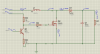
I'll show you the basic circuit that I want to made. Is a dc-dc boost 1.2V - 5V to 12Vout, 100W out. The bipolar was for making a drive for the mosfet, and as you said, placing R2 wasn't a good idea. My main problem is that I can't activate the mosfet.
The circuit you showed is a voltage booster that should have a continuous input from an oscillator, not just one pulse.
Thanks for the calculator. What mosfet shall I use then? It's incredibe hard to pick the good one
As I said before, if I use a generic npn bipolar instead, it works fine, but even if I try with a generic nmosfet it doesn't work. I also tried with a 10V amplitud pulse, but it seems it doesn't wants to be activated. So I think my problem is that I dont know how to trigger the mosfet (?)
There are hundreds of modern Mosfets that have a very low on resistance when the gate-source voltage is only 4.5V. Try an IRF3711.
Try a square wave 5V or 10V peak signal as the input.
Your inductor has no "H" for its value in Henries. Then maybe your SIM program sees it as a very low value resistor.
Why did you add a resistor in series with the source pin of the Mosfet?
I think that was probably my fault, I pointed out that when the FET was switched on, it was almost a dead short. However, I had overlooked the inductor at that point. A 1-ohm resistor really doesn't make much of a difference either way, but it should definitely be removed.
I don't really understand why the OP is using a BJT to switch the FET instead of controlling the FET directly....?
I vaguely remember having problems with just using signal sources to drive transistors in Proteus. It's possible that's what's happening to yours. Try replacing the signal source with a push-button connected between the gate and +5v, and a resistor (say, 10k) between the gate and ground. Then operate the pushbutton and see if the FET switches.
Ronv, that's exactly what I'm searching for ! But still can't get it Uu, and I dont have spice
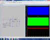
DerStrom8, I tried this:
Do you see that the FET is not activated? Even if I connect it directly to the 5V source ! I also tried placing a button, and I get this error:
DELMIN increased to 2.2e-16 due to lack of time precision
transient GMIN stepping at time 1.2
TRAN: Timestep too small, timestep=2.77e-16: trouble with instance D1
I'm kind of guessing, but it looks like maybe your inductor has very low resistance so 264 amps thru the fet. Since it can't do that it may show 5 volts still. Try it with a resistor - say 1 ohm in place of the inductor until you can see it switch.
This site uses cookies to help personalise content, tailor your experience and to keep you logged in if you register.
By continuing to use this site, you are consenting to our use of cookies.

")