Electro Tech is an online community (with over 170,000 members) who enjoy talking about and building electronic circuits, projects and gadgets. To participate you need to register. Registration is free. Click here to register now.
Welcome to our site! Electro Tech is an online community (with over 170,000 members) who enjoy talking about and building electronic circuits, projects and gadgets. To participate you need to register. Registration is free. Click here to register now.
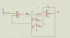
I've attached a general schematic of triple wave generator with op-amp so i need to know the concept of genrating such waveform or maybe tutorial website, and any comment will be appreciated!
thanks.
U2 is an integrator in that it will convert the square wave input to a triangle wave. With the resistor on the inverting input the inverting input is at a virtual ground and thus the input becomes a constant current source for the capacitor connected between the inverting input and the output. When a capacitor is charged with a constant current current the capacitor charges in a linear mode instead of an expoential (sic) curve.
On the input when the square wave is at 0 the resistor on the inverting input discharges the capacitor in a linear mode giving a full cycle triangle wave.
U1 is a square wave oscillator, but it is questionable if the duty cycle is
50%, so it is questionable if the triangle wave from U2 has the same rise and fall times.
No question. The 'reference voltage' adjust pot adjusts the duty-cycle. The zeners (if they are matched) ensure that the positive-going and negative-going output voltages of the square wave are the same.
No question. The 'reference voltage' adjust pot adjusts the duty-cycle. The zeners (if they are matched) ensure that the positive-going and negative-going output voltages of the square wave are the same.
Errrmmmm....
The duty cycle will always be 50% if the zeners are matched, because it's only the levels at the zener node that determine the slopes of the integrator. If the zener clamp levels are symmetrical around GND, the slope magnitudes will be equal. The control voltage actually changes the offset voltage (DC level) of the triangle wave.
The bottom line is you can add any low frequency waveform to the triangle wave by applying it to the input. The behavior gets really strange when the input frequency is greater than half the natural oscillatin frequency. If the input amplitude is fairly high, it starts to injection lock.
If you want to change the duty cycle,you can connect a variable voltage to the noninverting input of the integrator.
As you can guess, I ran some simulations to make these half-assed conclusions. You need to build it or simulate it, or be a lot smarter than I am, to figure out all the effects of the input voltage.
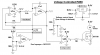
I didn't analyse my integrator circuit, I built it.
Its square-wave and triangle-wave symmetry look good and the circuit works fine.
I selected the low PWM frequency of only 2kHz so I can hear the motor whine as a warning before its speed winds up.
This site uses cookies to help personalise content, tailor your experience and to keep you logged in if you register.
By continuing to use this site, you are consenting to our use of cookies.